Cirkit Designer
Your all-in-one circuit design IDE
Home /
Project Documentation
Arduino UNO-Based Ultrasonic Distance Sensor with Bluetooth and LED Indicator
Circuit Documentation
Summary
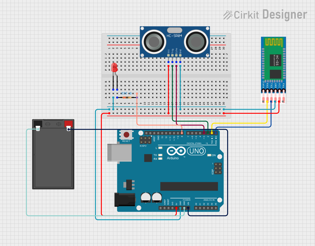
This document provides a detailed overview of a circuit that includes an Arduino UNO microcontroller, an HC-05 Bluetooth module, an HC-SR04 Ultrasonic Sensor, a red LED, a resistor, and a battery. The circuit is designed to interface with various sensors and actuators, with the Arduino UNO serving as the central control unit.
Component List
Arduino UNO
- Description: A microcontroller board based on the ATmega328P.
- Pins: UNUSED, IOREF, Reset, 3.3V, 5V, GND, Vin, A0, A1, A2, A3, A4, A5, SCL, SDA, AREF, D13, D12, D11, D10, D9, D8, D7, D6, D5, D4, D3, D2, D1, D0
HC-05 Bluetooth Module
- Description: A Bluetooth module for wireless communication.
- Pins: EN, VCC, GND, TXD, RXD, STATE
HC-SR04 Ultrasonic Sensor
- Description: An ultrasonic sensor for distance measurement.
- Pins: VCC, TRIG, ECHO, GND
LED: Two Pin (red)
- Description: A red LED for visual indication.
- Pins: cathode, anode
Resistor
- Description: A resistor with a resistance of 220 Ohms.
- Pins: pin1, pin2
- Properties:
- Resistance: 220 Ohms
Battery
- Description: A power source for the circuit.
- Pins: -, +
Wiring Details
Arduino UNO
- GND: Connected to the GND pins of the HC-05 Bluetooth Module, HC-SR04 Ultrasonic Sensor, and the cathode of the red LED.
- 5V: Connected to the VCC pins of the HC-05 Bluetooth Module and HC-SR04 Ultrasonic Sensor.
- Vin: Connected to the + pin of the battery.
- D8: Connected to pin2 of the resistor.
- D2: Connected to the TRIG pin of the HC-SR04 Ultrasonic Sensor.
- D3: Connected to the ECHO pin of the HC-SR04 Ultrasonic Sensor.
- D1: Connected to the RXD pin of the HC-05 Bluetooth Module.
- D0: Connected to the TXD pin of the HC-05 Bluetooth Module.
HC-05 Bluetooth Module
- GND: Connected to the GND pin of the Arduino UNO.
- VCC: Connected to the 5V pin of the Arduino UNO.
- RXD: Connected to the D1 pin of the Arduino UNO.
- TXD: Connected to the D0 pin of the Arduino UNO.
HC-SR04 Ultrasonic Sensor
- GND: Connected to the GND pin of the Arduino UNO.
- VCC: Connected to the 5V pin of the Arduino UNO.
- TRIG: Connected to the D2 pin of the Arduino UNO.
- ECHO: Connected to the D3 pin of the Arduino UNO.
LED: Two Pin (red)
- cathode: Connected to the GND pin of the Arduino UNO.
- anode: Connected to pin1 of the resistor.
Resistor
- pin1: Connected to the anode of the red LED.
- pin2: Connected to the D8 pin of the Arduino UNO.
Battery
- -: Connected to the GND pin of the Arduino UNO.
- +: Connected to the Vin pin of the Arduino UNO.
Documented Code
Arduino UNO Code (sketch.ino)
void setup() {
  // put your setup code here, to run once:

}

void loop() {
  // put your main code here, to run repeatedly:

}
Additional Documentation (documentation.txt)
This document provides a comprehensive overview of the circuit, including a summary, component list, wiring details, and documented code.