
ESP32-Based Smart Height and Weight Measurement System with Ultrasonic and Load Sensors
View and Edit Project In Cirkit Designer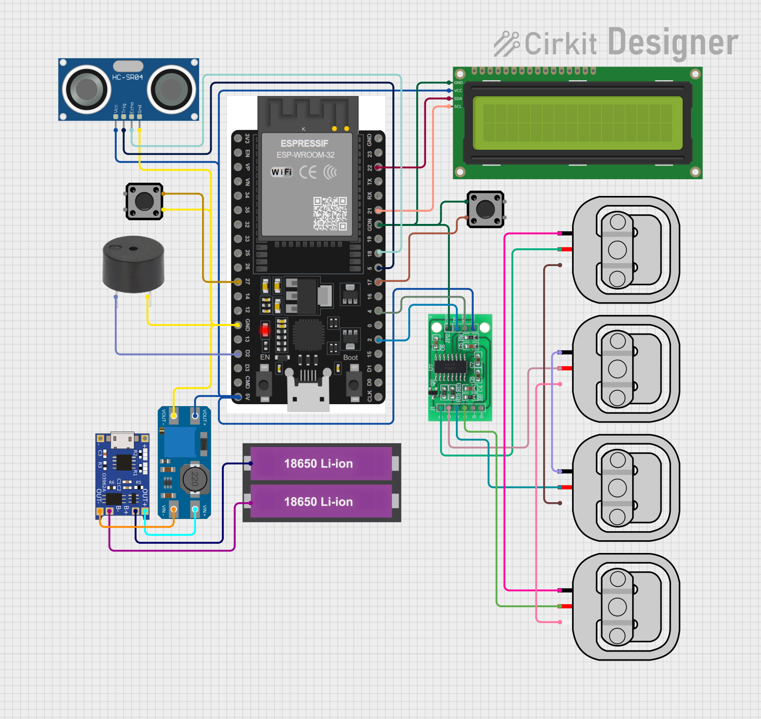
Circuit Documentation
Summary
This circuit is designed to measure height and weight using an ESP32 microcontroller. It integrates various sensors and components, including an ultrasonic sensor for height measurement, load sensors for weight measurement, an I2C LCD for display, and a tactile switch for mode selection. The system is powered by a 18650 Li-ion battery and includes a TP4056 for battery management and an MT3608 for voltage regulation.
Component List
ESP32 38 PINS
- Description: Microcontroller with Wi-Fi and Bluetooth capabilities.
- Pins: GND, 23, 22/SCL, 1, 2, 21/SDA, 19, 18, 5, 17/TX2, 16/RX2, 4, 0, 15, D1, D0, CLK, 3V3, EN, VP, VN, 34, 35, 32, 33, 25, 26, 27, 14, 12, 13, D2, D3, 11, 5V/VIN
HC-SR04 Ultrasonic Sensor
- Description: Ultrasonic sensor for distance measurement.
- Pins: VCC, TRIG, ECHO, GND
Load Sensor - 50kg
- Description: Load sensor for weight measurement.
- Pins: W, R, B
TP4056
- Description: Lithium battery charger module.
- Pins: OUT-, B-, B+, OUT+, IN-, IN+
16x2 I2C LCD
- Description: LCD display with I2C interface.
- Pins: GND, VCC, SDA, SCL
Tactile Switch Buttons - 12mm Square
- Description: Tactile switch for user input.
- Pins: 3, 1, 4, 2
18650 Li-ion Battery x 2
- Description: Rechargeable lithium-ion battery.
- Pins: +, -
HX711 - Bridge Sensor Interface
- Description: Load cell amplifier and ADC.
- Pins: E+, E-, A-, A+, B-, B+, GND - GROUND, DATA (OUT), SCK - CLOCK (IN), 3.3/3.5V Supply
MT3608
- Description: DC-DC step-up converter.
- Pins: VOUT+, VIN+, VOUT-, VIN-
Buzzer
- Description: Audio signaling device.
- Pins: PIN, GND
Wiring Details
ESP32 38 PINS
- GND: Connected to GND of 16x2 I2C LCD, Tactile Switch Button, HX711, MT3608, HC-SR04 Ultrasonic Sensor, and Buzzer.
- 22/SCL: Connected to SDA of 16x2 I2C LCD.
- 21/SDA: Connected to SCL of 16x2 I2C LCD.
- 18: Connected to ECHO of HC-SR04 Ultrasonic Sensor.
- 5: Connected to TRIG of HC-SR04 Ultrasonic Sensor.
- 17/TX2: Connected to pin 1 of Tactile Switch Button.
- 4: Connected to SCK - CLOCK (IN) of HX711.
- 2: Connected to DATA (OUT) of HX711.
- 27: Connected to pin 4 of Tactile Switch Button.
- D2: Connected to PIN of Buzzer.
- 5V/VIN: Connected to VOUT+ of MT3608.
HC-SR04 Ultrasonic Sensor
- VCC: Connected to VOUT+ of MT3608.
- TRIG: Connected to pin 5 of ESP32.
- ECHO: Connected to pin 18 of ESP32.
- GND: Connected to GND of ESP32.
Load Sensor - 50kg
- W: Connected to W of another Load Sensor.
- R: Connected to E+ of HX711.
- B: Connected to B of another Load Sensor.
TP4056
- OUT-: Connected to VIN- of MT3608.
- B-: Connected to - of 18650 Li-ion Battery.
- B+: Connected to + of 18650 Li-ion Battery.
- OUT+: Connected to VIN+ of MT3608.
16x2 I2C LCD
- GND: Connected to GND of ESP32.
- VCC: Connected to VOUT+ of MT3608.
- SDA: Connected to pin 22/SCL of ESP32.
- SCL: Connected to pin 21/SDA of ESP32.
Tactile Switch Buttons - 12mm Square
- Pin 1: Connected to pin 17/TX2 of ESP32.
- Pin 2: Connected to GND of ESP32.
- Pin 3: Connected to GND of Buzzer.
- Pin 4: Connected to pin 27 of ESP32.
18650 Li-ion Battery x 2
- +: Connected to B+ of TP4056.
- -: Connected to B- of TP4056.
HX711 - Bridge Sensor Interface
- E+: Connected to R of Load Sensor.
- E-: Connected to R of another Load Sensor.
- A+: Connected to R of another Load Sensor.
- A-: Connected to R of another Load Sensor.
- B+: Not connected.
- B-: Not connected.
- GND - GROUND: Connected to GND of ESP32.
- DATA (OUT): Connected to pin 2 of ESP32.
- SCK - CLOCK (IN): Connected to pin 4 of ESP32.
- 3.3/3.5V Supply: Connected to VOUT+ of MT3608.
MT3608
- VOUT+: Connected to VCC of 16x2 I2C LCD, VCC of HC-SR04 Ultrasonic Sensor, 5V/VIN of ESP32, and 3.3/3.5V Supply of HX711.
- VIN+: Connected to OUT+ of TP4056.
- VOUT-: Connected to GND of ESP32.
- VIN-: Connected to OUT- of TP4056.
Buzzer
- PIN: Connected to D2 of ESP32.
- GND: Connected to GND of Tactile Switch Button.
Documented Code
#include <Wire.h>
#include <LiquidCrystal_I2C.h>
#include <HX711.h>

// Ultrasonic Sensor Pins
const int trigPin = 5;   // Pin Trigger HC-SR04
const int echoPin = 18;  // Pin Echo HC-SR04

// Load Cell Pins
const int pinDOUT = 2;   // Pin DOUT Load Cell
const int pinSCK = 4;    // Pin SCK Load Cell

// I2C Custom Pins
const int I2C_SDA = 21;  // SDA Pin
const int I2C_SCL = 22;  // SCL Pin

// LCD I2C
LiquidCrystal_I2C lcd(0x27, 16, 2);

// HX711 Load Cell
HX711 scale;

// Pin untuk tombol mode
const int buttonPin = 17;  // Tombol untuk berganti mode

// Mode sensor height: Balita (100 cm) atau Dewasa (200 cm)
long sensorHeight = 200;  // Default mode: Dewasa

// Variabel untuk membaca tombol
int buttonState = 0;  // Variabel untuk membaca keadaan tombol
int lastButtonState = 0;  // Variabel untuk menyimpan keadaan tombol sebelumnya
unsigned long lastDebounceTime = 0;  // Waktu terakhir tombol dibaca
unsigned long debounceDelay = 50;  // Debounce delay untuk tombol

void setup() {
  Serial.begin(115200);

  // Initialize I2C
  Wire.begin(I2C_SDA, I2C_SCL);

  // Initialize LCD
  lcd.init();
  lcd.backlight();

  // Initialize Load Cell
  scale.begin(pinDOUT, pinSCK);
  scale.set_scale(0.42);  // Adjust calibration factor
  scale.tare();           // Reset scale to zero

  // Initialize Ultrasonic Sensor
  pinMode(trigPin, OUTPUT);
  pinMode(echoPin, INPUT);

  // Initialize button pin
  pinMode(buttonPin, INPUT_PULLUP);

  // Initial LCD Display
  lcd.setCursor(0, 0);
  lcd.print("NutriGrowth");
  lcd.setCursor(0, 1);
  lcd.print("V 1.0");
  delay(2000); // Pause to let user know system is starting
  lcd.clear();
}

void loop() {
  // Membaca status tombol dan mengubah mode jika tombol ditekan
  int reading