
Arduino UNO-Based Security System with PIR Sensor and Fingerprint Scanner
View and Edit Project In Cirkit Designer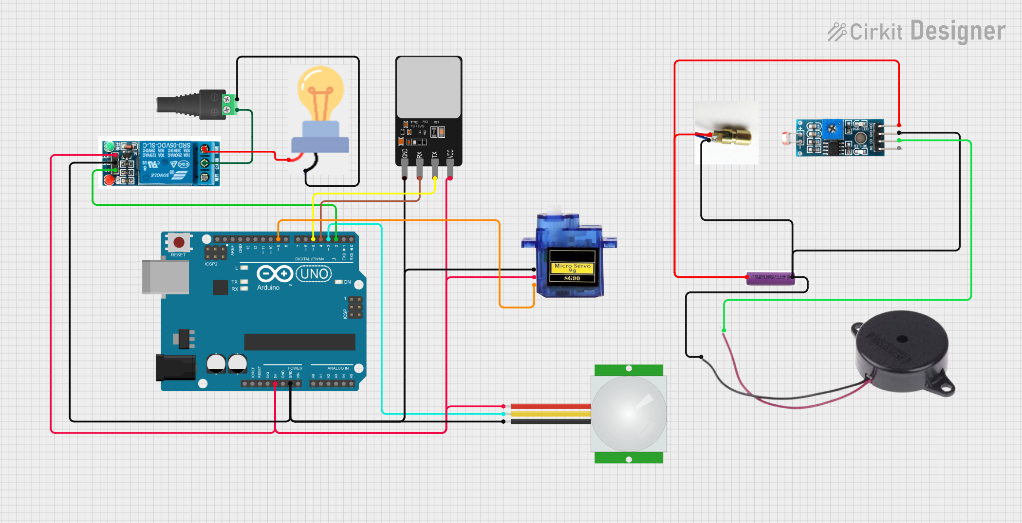
Circuit Documentation
Summary of the Circuit
This circuit is designed to interface various components with an Arduino UNO microcontroller. The components include a PIR sensor, a bulb, a 5V relay, a 2.1mm Barrel Jack with Terminal Block, a Module LDR, a Laser Diode, a Buzzer, a 3.7V battery, a Fingerprint Scanner, and a Micro servo 9G. The circuit is powered by the Arduino UNO's 5V output and a 3.7V battery. The relay controls the power to the bulb, while the PIR sensor and Module LDR provide input signals to the Arduino. The Fingerprint Scanner is interfaced for biometric input, and the Micro servo 9G is controlled via PWM. The Laser Diode and Buzzer are also part of the circuit, with the Buzzer being activated by the Module LDR's digital output.
Component List
Arduino UNO
- Microcontroller board based on the ATmega328P
- Provides 14 digital input/output pins, 6 analog inputs, a 16 MHz quartz crystal, a USB connection, a power jack, an ICSP header, and a reset button.
PIR Sensor
- Passive Infrared Sensor used for motion detection
- Outputs a signal when motion is detected.
Bulb
- An electric light source
- Powered by the relay when activated.
5V Relay
- Electromechanical switch used for controlling high power devices
- Has Normally Open (NO), Common (COM), and Normally Closed (NC) contacts.
2.1mm Barrel Jack with Terminal Block
- Power connector typically used for DC power input
- Connects to an external power source.
Module LDR (Light Dependent Resistor)
- A sensor module with an LDR that changes resistance with light intensity
- Provides both analog and digital outputs.
Laser Diode
- A semiconductor device that emits coherent light when current is applied.
Buzzer
- An audio signaling device
- Activated by the digital output from the Module LDR.
3.7V Battery
- A power source for the circuit
- Provides power to the Module LDR, Laser Diode, and Buzzer.
Fingerprint Scanner
- Biometric sensor for capturing fingerprints
- Interfaces with the Arduino for authentication purposes.
Micro servo 9G
- A small and lightweight servo motor
- Controlled by PWM signal from the Arduino.
Wiring Details
Arduino UNO
- 5V: Connected to the 5V relay, Micro servo 9G, Fingerprint Scanner, and PIR sensor.
- GND: Common ground for the 5V relay, Micro servo 9G, Fingerprint Scanner, and PIR sensor.
- D9: PWM output to Micro servo 9G.
- D5: TX to Fingerprint Scanner.
- D4: RX from Fingerprint Scanner.
- D3: Digital input from PIR sensor.
- D2: Digital output to 5V relay.
PIR Sensor
- VDD: Connected to 5V from Arduino UNO.
- SIG: Signal output to D3 on Arduino UNO.
- GND: Connected to common ground.
Bulb
- Power: Connected to Normally Closed contact of the 5V relay.
- GND: Connected to NEG of the 2.1mm Barrel Jack with Terminal Block.
5V Relay
- VCC: Connected to 5V from Arduino UNO.
- GND: Connected to common ground.
- In: Control input from D2 on Arduino UNO.
- Normally Closed: Connected to the bulb.
- Common terminal: Connected to POS of the 2.1mm Barrel Jack with Terminal Block.
2.1mm Barrel Jack with Terminal Block
- POS: Connected to Common terminal of the 5V relay.
- NEG: Connected to GND of the bulb.
Module LDR
- VCC: Connected to + of the 3.7V battery.
- GND: Connected to common ground.
- DO: Digital output to POSITIVE of the Buzzer.
Laser Diode
- Positive: Connected to + of the 3.7V battery.
- Negative: Connected to common ground.
Buzzer
- POSITIVE: Connected to DO of the Module LDR.
- NEGATIVE: Connected to common ground.
3.7V Battery
- +: Connected to VCC of the Module LDR and positive of the Laser Diode.
- -: Connected to common ground.
Fingerprint Scanner
- VCC: Connected to 5V from Arduino UNO.
- TX: Connected to D5 on Arduino UNO.
- RX: Connected to D4 on Arduino UNO.
- GND: Connected to common ground.
Micro servo 9G
- +5V: Connected to 5V from Arduino UNO.
- GND: Connected to common ground.
- PWM: Controlled by D9 on Arduino UNO.
Documented Code
Arduino UNO Code (sketch.ino)
void setup() {
  // put your setup code here, to run once:

}

void loop() {
  // put your main code here, to run repeatedly:

}
Note: The provided code is a template and does not contain any functional code. It needs to be populated with the logic to control and interact with the connected components based on the requirements of the circuit.