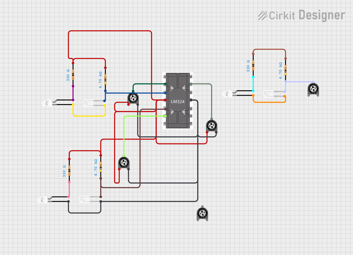
LM324-Based Analog Light Sensor with LED Indicators

Circuit Documentation
Summary
The circuit in question appears to be an analog signal processing circuit utilizing an LM324 operational amplifier (op-amp), several resistors, LEDs, phototransistors, and trimmer potentiometers. The LM324 is a quad op-amp, which means it contains four independent op-amps in one package. This circuit likely uses the LM324 for amplifying or conditioning signals from the phototransistors, which are sensors that change their electrical properties in response to light. The resistors set biasing conditions and limit current, while the trimmer potentiometers allow for adjustable resistance, which can be used to set thresholds or gain levels. The LEDs serve as indicators or for visual feedback.
Component List
LM324 Quad Operational Amplifier
- Description: A quad operational amplifier that can operate from a single power supply and has true differential inputs.
- Purpose: Used for signal amplification and conditioning.
Resistors
- Description: Passive electrical components that provide resistance to the flow of electric current.
- Purpose: Used to set biasing conditions, limit current, and form part of the feedback network for the op-amps.
LEDs: Two Pin (white)
- Description: Light Emitting Diodes that emit white light when forward-biased.
- Purpose: Serve as visual indicators or for feedback in the circuit.
Phototransistors
- Description: Semiconductors that change their conductivity with the amount of light falling on them.
- Purpose: Act as light sensors, providing an electrical signal in response to light intensity.
Trimmer Potentiometers
- Description: Variable resistors with three terminals, used to adjust circuit elements.
- Purpose: Provide an adjustable resistance to set thresholds or adjust signal levels.
Wiring Details
LM324 Quad Operational Amplifier
+ in 1: Connected to the collector of a phototransistor and a 4700 Ohm resistor.VCC: Connected to the positive supply voltage through various resistors.+ in 2: Connected to the collector of another phototransistor and a 4700 Ohm resistor.- in 2: Connected to the wiper of a trimmer potentiometer.GND: Connected to the emitters of phototransistors and the cathodes of LEDs.- in 4: Connected to the wiper of another trimmer potentiometer.- in 1: Connected to the wiper of a trimmer potentiometer.
Resistors
330 Ohms: Connected to the anodes of LEDs.4700 Ohms: Connected between the collectors of phototransistors and the non-inverting inputs of the LM324 op-amp.
LEDs: Two Pin (white)
Cathode: Connected to the emitters of phototransistors and ground.Anode: Connected to a 330 Ohm resistor.
Phototransistors
C: Collector connected to a 4700 Ohm resistor and the non-inverting input of the LM324 op-amp.E: Emitter connected to the cathode of an LED and ground.
Trimmer Potentiometers
Leg1: Connected to the positive supply voltage.Wiper: Connected to the inverting inputs of the LM324 op-amp.Leg2: Connected to ground.
Documented Code
No code has been provided for any microcontrollers in the circuit. If the circuit includes a microcontroller or any programmable device, please provide the relevant code for documentation.