Cirkit Designer
Your all-in-one circuit design IDE
Home /
Project Documentation
Arduino UNO Controlled Stepper Motor with ULN2003A Driver
Circuit Documentation
Summary
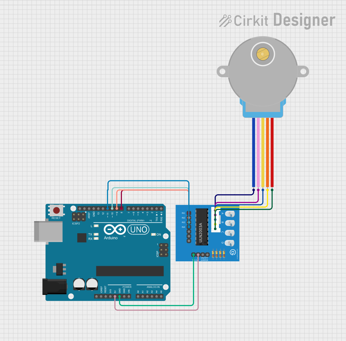
This circuit is designed to control a 28BYJ-48 stepper motor using an Arduino UNO and a ULN2003A breakout board. The Arduino UNO sends control signals to the ULN2003A, which in turn drives the stepper motor. The circuit allows for precise control of the stepper motor's position via serial input.
Component List
28BYJ-48 Stepper Motor
- Description: A small, inexpensive stepper motor commonly used in various applications.
- Pins: BLUE, PINK, YELLOW, ORANGE, RED
ULN2003A Breakout Board
- Description: A Darlington transistor array used to drive the stepper motor.
- Pins: In 1, In 2, In 3, In 4, In 5, In 6, In 7, 0V, +5V, ON/OFF jumper switch, BLUE wire, PINK wire, YELLOW wire, ORANGE wire, RED wire
Arduino UNO
- Description: A microcontroller board based on the ATmega328P, used to control the stepper motor.
- Pins: UNUSED, IOREF, Reset, 3.3V, 5V, GND, Vin, A0, A1, A2, A3, A4, A5, SCL, SDA, AREF, D13, D12, D11, D10, D9, D8, D7, D6, D5, D4, D3, D2, D1, D0
Wiring Details
28BYJ-48 Stepper Motor
- BLUE wire connected to BLUE wire on ULN2003A breakout board
- PINK wire connected to PINK wire on ULN2003A breakout board
- YELLOW wire connected to YELLOW wire on ULN2003A breakout board
- ORANGE wire connected to ORANGE wire on ULN2003A breakout board
- RED wire connected to RED wire on ULN2003A breakout board
ULN2003A Breakout Board
- In 1 connected to D8 on Arduino UNO
- In 2 connected to D9 on Arduino UNO
- In 3 connected to D10 on Arduino UNO
- In 4 connected to D11 on Arduino UNO
- 0V connected to GND on Arduino UNO
- +5V connected to 5V on Arduino UNO
Arduino UNO
- D8 connected to In 1 on ULN2003A breakout board
- D9 connected to In 2 on ULN2003A breakout board
- D10 connected to In 3 on ULN2003A breakout board
- D11 connected to In 4 on ULN2003A breakout board
- GND connected to 0V on ULN2003A breakout board
- 5V connected to +5V on ULN2003A breakout board
Code Documentation
Arduino UNO Code
#include <Stepper.h>
#define STEPS 32

Stepper stepper(STEPS, 8, 9, 10, 11);
int val = 0;

void setup() {
    Serial.begin(9600);
    stepper.setSpeed(200);
}

void loop() {
    if (Serial.available() > 0) {
        val = Serial.parseInt();
        stepper.step(val);
        Serial.println(val);
    }
}
- Libraries Used:
Stepper.h - Stepper Motor Configuration: The stepper motor is configured with 32 steps per revolution.
- Pin Configuration: The stepper motor is controlled via pins 8, 9, 10, and 11 on the Arduino UNO.
- Serial Communication: The Arduino listens for serial input to determine the number of steps to move the motor.
- Speed Setting: The stepper motor speed is set to 200 RPM.
This code initializes the stepper motor and sets up serial communication. In the main loop, it reads the number of steps from the serial input and moves the stepper motor accordingly.