
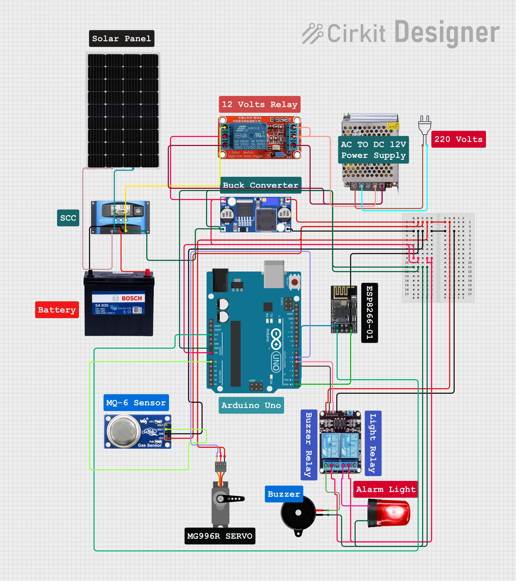
Circuit Documentation
Summary
This circuit is designed to manage and utilize solar energy efficiently. It includes a solar panel, an MPPT (Maximum Power Point Tracking) Solar Charge Controller (SCC), a 12V 200Ah battery, a buck converter, relays, an Arduino UNO, a WiFi module, various sensors, and actuators. The system is capable of monitoring and controlling various components to optimize energy usage and provide alerts.
Component List
Solar Panel
- Description: Converts sunlight into electrical energy.
- Pins: +, -
MPPT SCC
- Description: Manages the power from the solar panel to charge the battery and supply power to the load.
- Pins: SOLAR+, SOLAR-, BATTERY+, BATTERY-, LOAD+, LOAD-
12V 200Ah Battery
- Description: Stores electrical energy for later use.
- Pins: GND, 12V
Buck Converter
- Description: Steps down the voltage from the battery to a lower voltage suitable for other components.
- Pins: IN+, IN-, OUT+, OUT-
12V Relay
- Description: Electrically operated switch used to control a high-power circuit with a low-power signal.
- Pins: NO, COM, NC, IN, DC-, DC+
POWER SUPPLY 12V 5AMP
- Description: Converts 220V AC to 12V DC.
- Pins: 220V Positive Pole (AC), 220V Negative Pole (AC), GND, GND (DC), 12V-24V Output (DC)
Arduino UNO
- Description: Microcontroller used for controlling and monitoring the circuit.
- Pins: UNUSED, IOREF, Reset, 3.3V, 5V, GND, Vin, A0, A1, A2, A3, A4, A5, SCL, SDA, AREF, D13, D12, D11, D10, D9, D8, D7, D6, D5, D4, D3, D2, D1, D0
Wifi Module ESP8266-01
- Description: Provides WiFi connectivity for the Arduino UNO.
- Pins: RX, GPIO0, GPIO2, GND, +3V3, Reset, CH-PD Chip power down, TX
MQ6
- Description: Gas sensor used to detect the presence of gas.
- Pins: VCC, GND, A0, DO
Servo
- Description: Actuator used for precise control of angular position.
- Pins: GND, VCC, PWM
Piezo Speaker
- Description: Produces sound when a voltage is applied.
- Pins: pin1, pin2
Siren
- Description: Produces a loud sound for alerts.
- Pins: Positive, Ground
2ch Relay
- Description: Dual-channel relay used to control multiple high-power circuits.
- Pins: NC, COM, NO, VCC, IN2, IN1, GND
Power 220V
- Description: Provides 220V AC power.
- Pins: hot wire, neutral wire
Wiring Details
Solar Panel
- + connected to SOLAR+ of MPPT SCC
- - connected to SOLAR- of MPPT SCC
MPPT SCC
- SOLAR+ connected to + of Solar Panel
- SOLAR- connected to - of Solar Panel
- BATTERY+ connected to 12V of 12V 200Ah Battery
- BATTERY- connected to GND of 12V 200Ah Battery
- LOAD+ connected to NO of 12V Relay
- LOAD- connected to GND of Arduino UNO, Ground of Siren, IN- of Buck Converter, pin1 of Piezo Speaker
12V 200Ah Battery
- 12V connected to BATTERY+ of MPPT SCC
- GND connected to BATTERY- of MPPT SCC
Buck Converter
- IN+ connected to COM of 2ch Relay, COM of 12V Relay
- IN- connected to LOAD- of MPPT SCC
- OUT+ connected to VCC of Servo, VCC of 2ch Relay, VCC of MQ6
- OUT- connected to GND of Wifi Module ESP8266-01, GND of 2ch Relay, GND of MQ6
12V Relay
- NO connected to LOAD+ of MPPT SCC
- COM connected to IN+ of Buck Converter
- NC connected to DC+ of 12V Relay
- IN connected to DC- of 12V Relay
- DC+ connected to 12V-24V Output (DC) of POWER SUPPLY 12V 5AMP
- DC- connected to GND (DC) of POWER SUPPLY 12V 5AMP
POWER SUPPLY 12V 5AMP
- 220V Positive Pole (AC) connected to hot wire of Power 220V
- 220V Negative Pole (AC) connected to neutral wire of Power 220V
- 12V-24V Output (DC) connected to DC+ of 12V Relay
- GND (DC) connected to DC- of 12V Relay
Arduino UNO
- GND connected to LOAD- of MPPT SCC
- Vin connected to COM of 2ch Relay
- 3.3V connected to +3V3 of Wifi Module ESP8266-01
- A0 connected to A0 of MQ6
- D6 connected to PWM of Servo
- D5 connected to IN1 of 2ch Relay
- D4 connected to IN2 of 2ch Relay
- D1 connected to RX of Wifi Module ESP8266-01
- D0 connected to TX of Wifi Module ESP8266-01
Wifi Module ESP8266-01
- GND connected to OUT- of Buck Converter
- +3V3 connected to 3.3V of Arduino UNO
- RX connected to D1 of Arduino UNO
- TX connected to D0 of Arduino UNO
MQ6
- VCC connected to OUT+ of Buck Converter
- GND connected to OUT- of Buck Converter
- A0 connected to A0 of Arduino UNO
Servo
- GND connected to OUT- of Buck Converter
- VCC connected to OUT+ of Buck Converter
- PWM connected to D6 of Arduino UNO
Piezo Speaker
- pin1 connected to LOAD- of MPPT SCC
- pin2 connected to NO of 2ch Relay
Siren
- Positive connected to NO of 2ch Relay
- Ground connected to LOAD- of MPPT SCC
2ch Relay
- NC connected to NO of 2ch Relay
- COM connected to Vin of Arduino UNO, COM of 12V Relay
- NO connected to pin2 of Piezo Speaker, Positive of Siren
- VCC connected to OUT+ of Buck Converter
- IN2 connected to D4 of Arduino UNO
- IN1 connected to D5 of Arduino UNO
- GND connected to OUT- of Buck Converter
Power 220V
- hot wire connected to 220V Positive Pole (AC) of POWER SUPPLY 12V 5AMP
- neutral wire connected to 220V Negative Pole (AC) of POWER SUPPLY 12V 5AMP
Documented Code
Arduino UNO Code (sketch.ino)
void setup() {
  // put your setup code here, to run once:

}

void loop() {
  // put your main code here, to run repeatedly:

}
Additional Documentation (documentation.txt)
This documentation provides a comprehensive overview of the circuit, including a summary, detailed component list, wiring details, and the code used in the microcontroller.