Solar-Powered Dual Input Safety Circuit with Automatic Transfer Switch and IoT Monitoring
Circuit Documentation
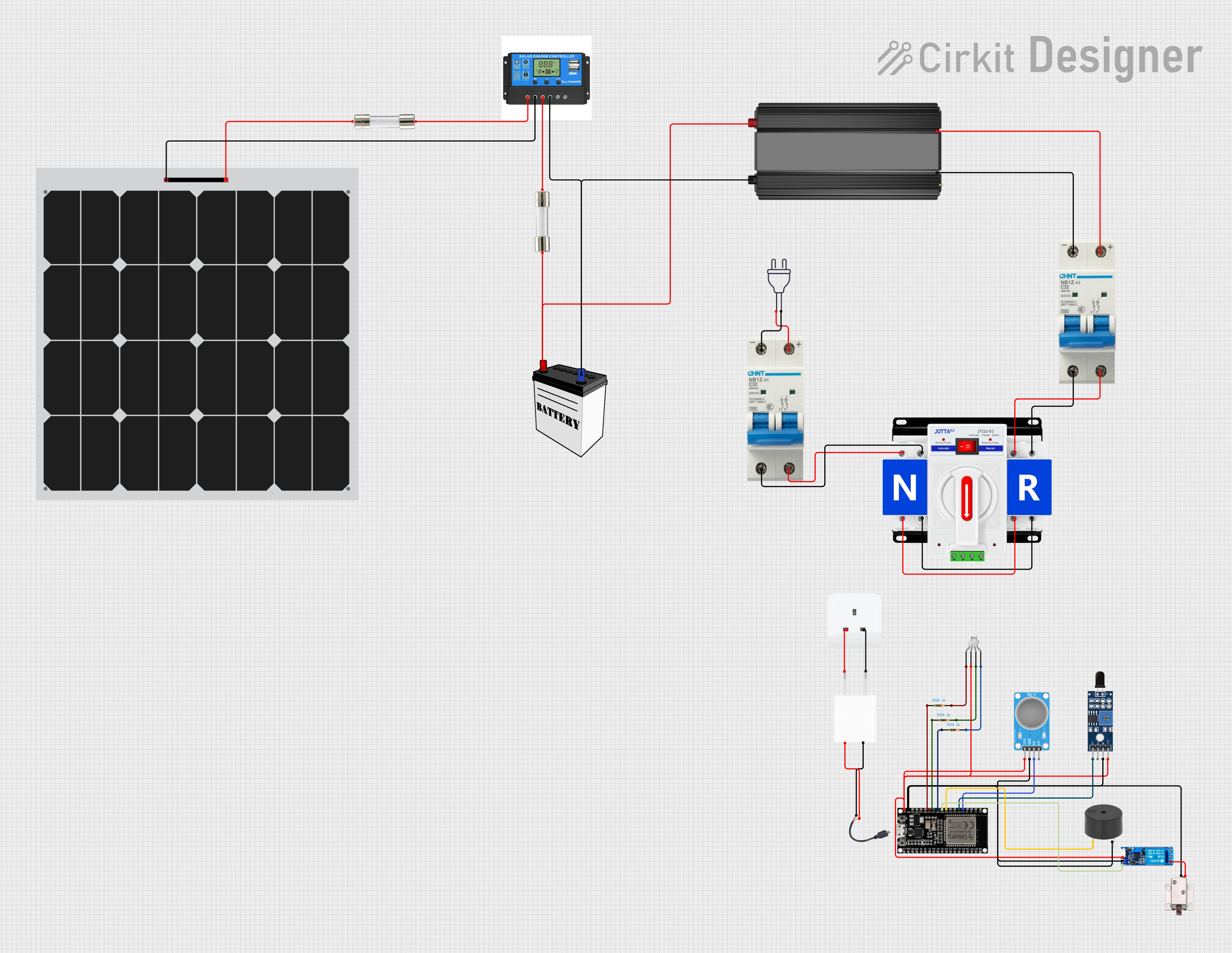
Summary
The circuit described in the provided information is a power management system that integrates solar power with a conventional 220V power supply. It includes safety features such as circuit breakers and fuses, a dual power automatic transfer switch for switching between solar and mains power, a charge controller for managing solar energy input, and a power inverter for converting DC to AC power. Additionally, the circuit incorporates an ESP32 microcontroller interfaced with various sensors and actuators, including an MQ-2 gas sensor, an SHT113 flame sensor, a buzzer, a relay module, and a 12V solenoid lock. The system also features a 5V adapter for power supply and an LED with resistors for indication purposes.
Component List
Circuit Breaker
- Description: A safety device designed to protect an electrical circuit from damage caused by excess current from an overload or short circuit.
- Pins:
-,+
Dual Power Automatic Transfer Switch
- Description: A device that automatically transfers a power supply from its primary source to a backup source when it senses a failure or outage in the primary source.
- Pins:
+,-
Solar Panel
- Description: A panel designed to absorb the sun's rays as a source of energy for generating electricity.
- Pins:
+,-
Charge Controller
- Description: A device that regulates the voltage and current coming from the solar panels going to the battery and prevents overcharging and may protect against overvoltage.
- Pins:
Solar Positive,Solar Negative,Battery Positive,Battery Negative,Load Positive,Load Negative
Power Inverter
- Description: An electronic device that changes direct current (DC) to alternating current (AC).
- Pins:
-,+
Power 220V
- Description: Represents the mains power supply with a standard voltage of 220V.
- Pins:
hot wire,neutral wire
Fuse
- Description: A safety device consisting of a strip of wire that melts and breaks an electric circuit if the current exceeds a safe level.
- Pins:
Terminal 1,Terminal 2
Socket
- Description: An electrical device receiving a plug or light bulb to make a connection.
- Pins:
earth,life,neutral
5V Adapter
- Description: A power supply that converts mains AC to 5V DC.
- Pins:
AC In 1,AC In 2,5V,GND
ESP32 38 PINS
- Description: A microcontroller with Wi-Fi and Bluetooth capabilities for smart applications.
- Pins:
GND,G23,G22,TXD,RXD,G21,G19,G18,G5,G17,G16,G4,G0,G2,G15,SDI,SD0,CLK,3V3,EN,SP,SN,G34,G35,G32,33,G25,G26,G27,G14,G12,G13,SD2,SD3,5V
MQ-2 SENSOR
- Description: A gas sensor used for detecting a wide range of gases including LPG, propane, methane, hydrogen, and smoke.
- Pins:
VCC,GND,A0,D0
Sensor SHT113 Flame
- Description: A flame sensor capable of detecting a flame or a light source of a wavelength in the range of 760nm-1100 nm.
- Pins:
A0,D0,GND,VCC
Buzzer
- Description: An audio signaling device, which may be mechanical, electromechanical, or piezoelectric.
- Pins:
PIN,GND
12V Solenoid Lock
- Description: An electronic lock that is actuated by an electrical current, typically used in door locking mechanisms.
- Pins:
VCC,GND
Relay Module 5V-30V
- Description: An electrically operated switch that allows you to turn on or off a circuit using voltage and/or current much higher than a microcontroller could handle.
- Pins:
common contact,normally open,normally closed,trigger,V-,V+
Micro USB to Cable (2 Pin)
- Description: A cable with a Micro USB connector on one end and two pins for power connections on the other.
- Pins:
Micro USB,+,-
LED: Four Pin
- Description: A four-pin LED with a common anode and three cathodes for red, green, and blue.
- Pins:
red cathode,common anode,green cathode,blue cathode
Resistor
- Description: A passive two-terminal electrical component that implements electrical resistance as a circuit element.
- Properties:
Resistance: 500 Ohms
12V Battery
- Description: A battery that provides a nominal voltage of 12 volts, commonly used in automotive and backup power applications.
- Pins:
VCC,GND
Wiring Details
Circuit Breaker to Power Inverter
- Circuit Breaker
-to Power Inverter- - Circuit Breaker
+to Power Inverter+
Circuit Breaker to Dual Power Automatic Transfer Switch
- Circuit Breaker
-to Dual Power Automatic Transfer Switch- - Circuit Breaker
+to Dual Power Automatic Transfer Switch+
Circuit Breaker to Power 220V
- Circuit Breaker
-to Power 220Vneutral wire - Circuit Breaker
+to Power 220Vhot wire
Dual Power Automatic Transfer Switch Interconnections
- Dual Power Automatic Transfer Switch
+to Dual Power Automatic Transfer Switch+ - Dual Power Automatic Transfer Switch
-to Dual Power Automatic Transfer Switch-
Solar Panel to Charge Controller
- Solar Panel
+to FuseTerminal 2to Charge ControllerSolar Positive - Solar Panel
-to Charge ControllerSolar Negative
Charge Controller to 12V Battery
- Charge Controller
Battery Positiveto FuseTerminal 2to 12V BatteryVCC - Charge Controller
Battery Negativeto 12V BatteryGND
Power Inverter to 12V Battery
- Power Inverter
+to 12V BatteryVCC - Power Inverter
-to 12V BatteryGND
Socket to 5V Adapter
- Socket
lifeto 5V AdapterAC In 1 - Socket
neutralto 5V AdapterAC In 2
Micro USB to Cable (2 Pin) to 5V Adapter
- Micro USB to Cable (2 Pin)
+to 5V Adapter5V - Micro USB to Cable (2 Pin)
-to 5V AdapterGND
ESP32 38 PINS to Sensors and Actuators
- ESP32 38 PINS
G34to MQ-2 SENSORA0 - ESP32 38 PINS
G35to Sensor SHT113 FlameA0 - ESP32 38 PINS
G25to BuzzerPIN - ESP32 38 PINS
G26to Relay Module 5V-30Vtrigger - ESP32 38 PINS
G27to Resistorpin1(for LED red cathode) - ESP32 38 PINS
G14to Resistorpin1(for LED green cathode) - ESP32 38 PINS
G12to Resistorpin1(for LED blue cathode)
Common Ground and VCC Connections
- ESP32 38 PINS
GNDto MQ-2 SENSORGND, Relay Module 5V-30VV-, BuzzerGND, 12V Solenoid LockGND, Sensor SHT113 FlameGND - ESP32 38 PINS
5Vto MQ-2 SENSORVCC, Relay Module 5V-30VV+, LED: Four Pincommon anode, Sensor SHT113 FlameVCC
Relay Module 5V-30V to 12V Solenoid Lock
- Relay Module 5V-30V
normally opento 12V Solenoid LockVCC
LED: Four Pin to Resistors
- LED: Four Pin
red cathodeto Resistorpin2(500 Ohms) - LED: Four Pin
green cathodeto Resistorpin2(500 Ohms) - LED: Four Pin
blue cathodeto Resistorpin2(500 Ohms)
Documented Code
No code was provided for the microcontrollers in the circuit. If code is available, it should be documented here with explanations for each function and how it interacts with the connected hardware components.