
Arduino UNO Controlled Robot with FlySky FS-IA6 and L298N Motor Driver
View and Edit Project In Cirkit Designer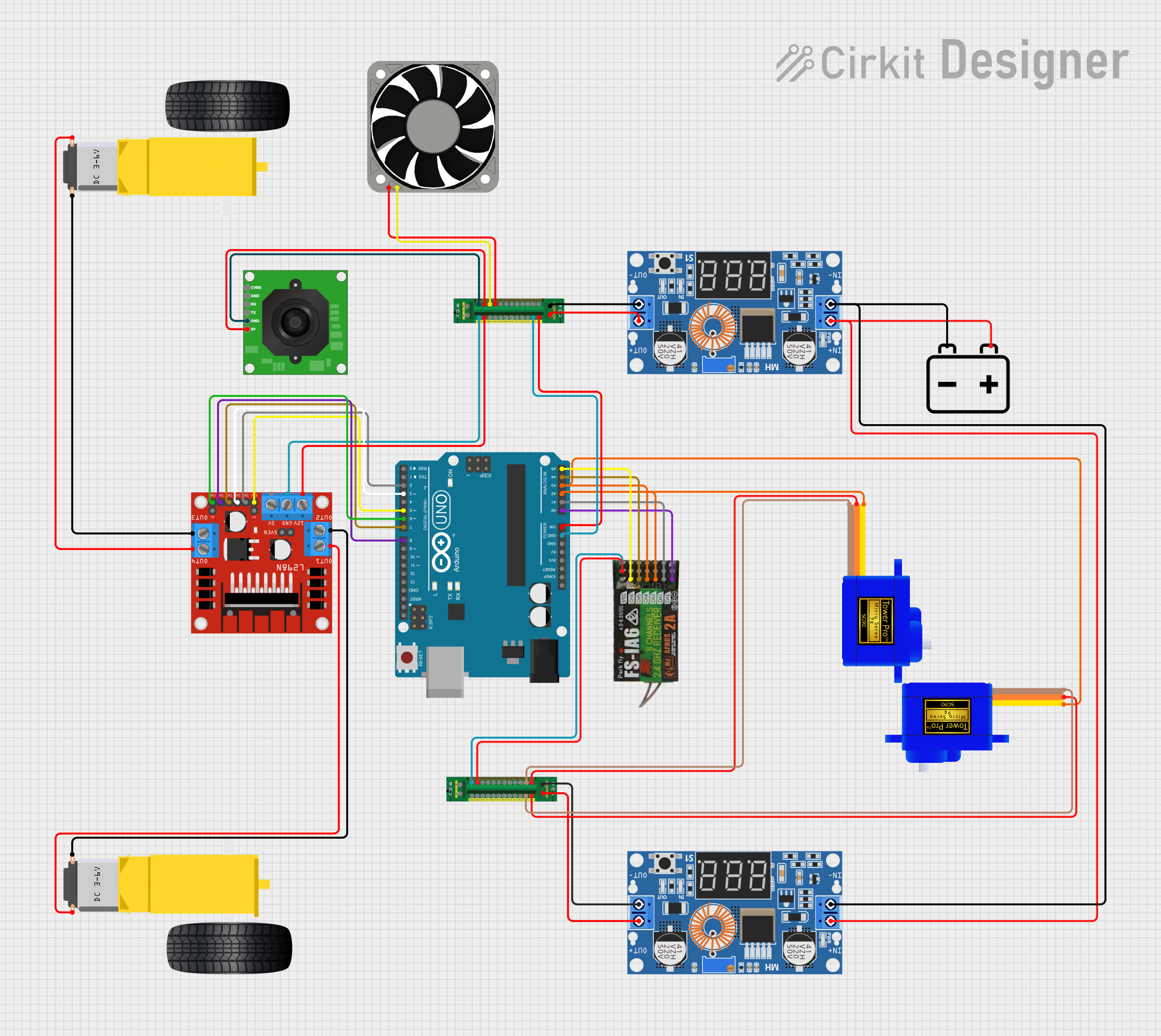
Circuit Documentation
Summary
This circuit is designed to control a robot with two DC motors and two servos. The motors are controlled via an L298N motor driver, and the servos are controlled directly from an Arduino UNO. The robot's movement is controlled by a FlySky FS-IA6 controller. The right joystick controls the motors for forward, left, and right movements, while the left joystick controls the servos for pan and tilt of an FPV camera.
Component List
TTL Serial JPEG Camera
- Pins: GND, RX, TX, CVBS, 5V
- Description: A camera module for capturing images and videos.
- Purpose: Captures images and videos for FPV (First Person View).
Servomotor SG90
- Pins: SIG, VCC, GND
- Description: A small servo motor.
- Purpose: Controls the pan and tilt of the FPV camera.
Gearmotor DC Wheels (Left)
- Pins: PIN1, PIN2
- Description: A DC motor for driving the left wheel.
- Purpose: Provides movement to the left wheel of the robot.
Gearmotor DC Wheels (Right)
- Pins: PIN1, PIN2
- Description: A DC motor for driving the right wheel.
- Purpose: Provides movement to the right wheel of the robot.
Power Distribution Board
- Pins: Output 1+, Input +, Input -, Output 2+, Output 2-, Output 3+, Output 4+, Output 5+, Output 1-, Output 4-, Output 3-, Output 5-, Output 6+, Output 6-, Output 7+, Output 7-, Output 8+, Output 8-, Output 9+, Output 9-, Output 10+, Output 10-, Output 11+, Output 11-, Output 12+, Output 12-, Output +, Output -
- Description: Distributes power to various components.
- Purpose: Provides power to all components in the circuit.
L298N DC Motor Driver
- Pins: OUT1, OUT2, 12V, GND, 5V, OUT3, OUT4, 5V-ENA-JMP-I, 5V-ENA-JMP-O, +5V-J1, +5V-J2, ENA, IN1, IN2, IN3, IN4, ENB
- Description: A motor driver for controlling DC motors.
- Purpose: Controls the DC motors for the robot's movement.
XL4015 5A DC Buck Step-down
- Pins: Output +, Output -, Input +, Input -
- Description: A DC-DC buck converter.
- Purpose: Steps down the voltage to a suitable level for the components.
40 Fan 12v
- Pins: +12V, -12V
- Description: A 12V cooling fan.
- Purpose: Provides cooling to the components.
12v Battery
- Pins: -, +
- Description: A 12V battery.
- Purpose: Provides power to the entire circuit.
FLYSKY FS-IA6
- Pins: CH1, 5V, GND, CH2, CH3, CH4, CH5, CH6, VCC
- Description: A receiver for the FlySky FS-IA6 controller.
- Purpose: Receives control signals from the FlySky FS-IA6 controller.
Arduino UNO
- Pins: UNUSED, IOREF, Reset, 3.3V, 5V, GND, Vin, A0, A1, A2, A3, A4, A5, SCL, SDA, AREF, D13, D12, D11, D10, D9, D8, D7, D6, D5, D4, D3, D2, D1, D0
- Description: A microcontroller board.
- Purpose: Controls the servos and motor driver based on input from the FlySky FS-IA6 receiver.
Wiring Details
TTL Serial JPEG Camera
- GND: Connected to Power Distribution Board (Output 6-)
- 5V: Connected to Power Distribution Board (Output 6+)
Servomotor SG90 (1)
- SIG: Connected to Arduino UNO (A2)
- VCC: Connected to Power Distribution Board (Output 1+)
- GND: Connected to Power Distribution Board (Output 1-)
Servomotor SG90 (2)
- SIG: Connected to Arduino UNO (A3)
- VCC: Connected to Power Distribution Board (Output 7+)
- GND: Connected to Power Distribution Board (Output 7-)
Gearmotor DC Wheels (Left)
- PIN1: Connected to L298N DC Motor Driver (OUT2)
- PIN2: Connected to L298N DC Motor Driver (OUT1)
Gearmotor DC Wheels (Right)
- PIN1: Connected to L298N DC Motor Driver (OUT4)
- PIN2: Connected to L298N DC Motor Driver (OUT3)
Power Distribution Board (1)
- Output 7-: Connected to Arduino UNO (GND)
- Output 7+: Connected to Arduino UNO (Vin)
- Output 6-: Connected to TTL Serial JPEG Camera (GND)
- Output 6+: Connected to TTL Serial JPEG Camera (5V)
- Output 12+: Connected to L298N DC Motor Driver (12V)
- Output 12-: Connected to L298N DC Motor Driver (GND)
- Output 5+: Connected to 40 Fan 12v (+12V)
- Output 5-: Connected to 40 Fan 12v (-12V)
- Input +: Connected to XL4015 5A DC Buck Step-down (Output +)
- Input -: Connected to XL4015 5A DC Buck Step-down (Output -)
Power Distribution Board (2)
- Output 1+: Connected to Servomotor SG90 (1) (VCC)
- Output 1-: Connected to Servomotor SG90 (1) (GND)
- Output 7+: Connected to Servomotor SG90 (2) (VCC)
- Output 7-: Connected to Servomotor SG90 (2) (GND)
- Output 6+: Connected to FLYSKY FS-IA6 (5V)
- Output 6-: Connected to FLYSKY FS-IA6 (GND)
L298N DC Motor Driver
- IN4: Connected to Arduino UNO (D8)
- IN3: Connected to Arduino UNO (D7)
- ENB: Connected to Arduino UNO (D6)
- ENA: Connected to Arduino UNO (D5)
- IN2: Connected to Arduino UNO (D3)
- IN1: Connected to Arduino UNO (D2)
- OUT2: Connected to Gearmotor DC Wheels (Left) (PIN1)
- OUT1: Connected to Gearmotor DC Wheels (Left) (PIN2)
- OUT4: Connected to Gearmotor DC Wheels (Right) (PIN1)
- OUT3: Connected to Gearmotor DC Wheels (Right) (PIN2)
- 12V: Connected to Power Distribution Board (Output 12+)
- GND: Connected to Power Distribution Board (Output 12-)
XL4015 5A DC Buck Step-down (1)
- Output +: Connected to Power Distribution Board (Input +)
- Output -: Connected to Power Distribution Board (Input -)
- Input +: Connected to XL4015 5A DC Buck Step-down (2) (Input +)
- Input -: Connected to XL4015 5A DC Buck Step-down (2) (Input -)
XL4015 5A DC Buck Step-down (2)
- Output +: Connected to Power Distribution Board (Input +)
- Output -: Connected to Power Distribution Board (Input -)
- Input +: Connected to XL4015 5A DC Buck Step-down (1) (Input +)
- Input -: Connected to XL4015 5A DC Buck Step-down (1) (Input -)
40 Fan 12v
- +12V: Connected to Power Distribution Board (Output 5+)
- -12V: Connected to Power Distribution Board (Output 5-)
12v Battery
- +: Connected to XL4015 5A DC Buck Step-down (1) (Input +)
- -: Connected to XL4015 5A DC Buck Step-down (1) (Input -)
FLYSKY FS-IA6
- CH1: Connected to Arduino UNO (A0)
- CH2: Connected to Arduino UNO (A1)
- **CH