
AC Circuit with Inductor and Capacitor Monitored by Multimeters
View and Edit Project In Cirkit Designer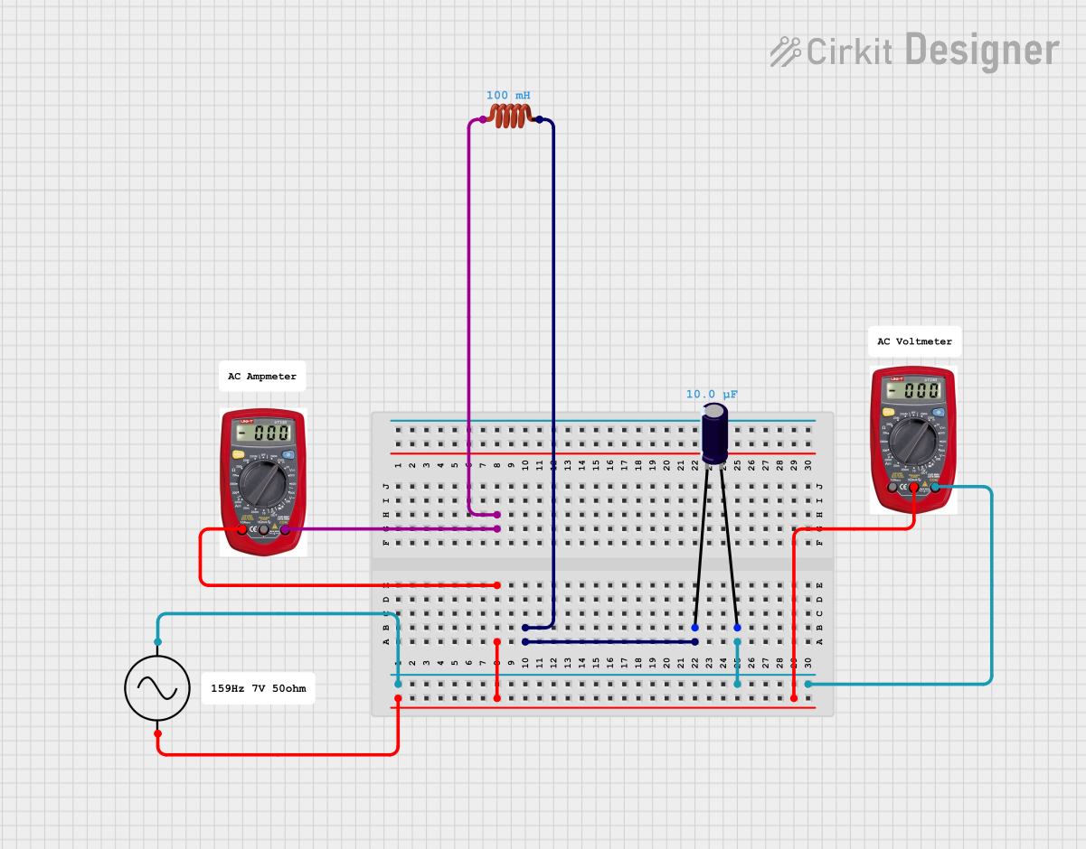
Circuit Documentation
Summary
This document provides a detailed overview of a circuit consisting of an AC supply, an electrolytic capacitor, an inductor, and two multimeters. The circuit is designed to measure various electrical parameters using the multimeters while the AC supply powers the circuit. The electrolytic capacitor and inductor form a basic LC circuit.
Component List
Electrolytic Capacitor
- Description: A polarized capacitor with a capacitance of 10 µF.
- Pins:
- Negative (-)
- Positive (+)
- Properties:
- Capacitance: 10 µF
Multimeter (1)
- Description: A device used to measure electrical parameters such as voltage, current, and resistance.
- Pins:
- COM
- V
- A
Multimeter (2)
- Description: A device used to measure electrical parameters such as voltage, current, and resistance.
- Pins:
- COM
- V
- A
AC Supply
- Description: A power supply that provides alternating current (AC) voltage.
- Pins:
- Positive (+ve)
- Negative (-ve)
Inductor
- Description: A passive electrical component that stores energy in a magnetic field.
- Pins:
- Pin 0
- Pin 1
- Properties:
- Inductance: 0.1 H
Comment (1)
- Description: A non-electrical component used for adding comments or notes in the circuit design.
Comment (2)
- Description: A non-electrical component used for adding comments or notes in the circuit design.
Comment (3)
- Description: A non-electrical component used for adding comments or notes in the circuit design.
Wiring Details
Electrolytic Capacitor
- Negative (-) Pin:
- Connected to Inductor Pin 1
- Positive (+) Pin:
- Connected to AC Supply Positive (+ve)
- Connected to Multimeter (2) COM
Multimeter (1)
- COM Pin:
- Connected to Inductor Pin 0
- V Pin:
- Connected to AC Supply Negative (-ve)
- Connected to Multimeter (2) A
- A Pin:
- Connected to AC Supply Negative (-ve)
- Connected to Multimeter (2) V
Multimeter (2)
- COM Pin:
- Connected to Electrolytic Capacitor Positive (+)
- V Pin:
- Connected to Multimeter (1) A
- A Pin:
- Connected to Multimeter (1) V
AC Supply
- Positive (+ve) Pin:
- Connected to Electrolytic Capacitor Positive (+)
- Connected to Multimeter (2) COM
- Negative (-ve) Pin:
- Connected to Multimeter (1) A
- Connected to Multimeter (2) V
Inductor
- Pin 0:
- Connected to Multimeter (1) COM
- Pin 1:
- Connected to Electrolytic Capacitor Negative (-)
Code
There is no embedded code associated with this circuit.
This document provides a comprehensive overview of the circuit, including a summary, detailed component list, wiring details, and code documentation.