Cirkit Designer
Your all-in-one circuit design IDE
Home /
Project Documentation
Arduino UNO Based IR-Controlled Relay Switching System

Circuit Documentation
Summary
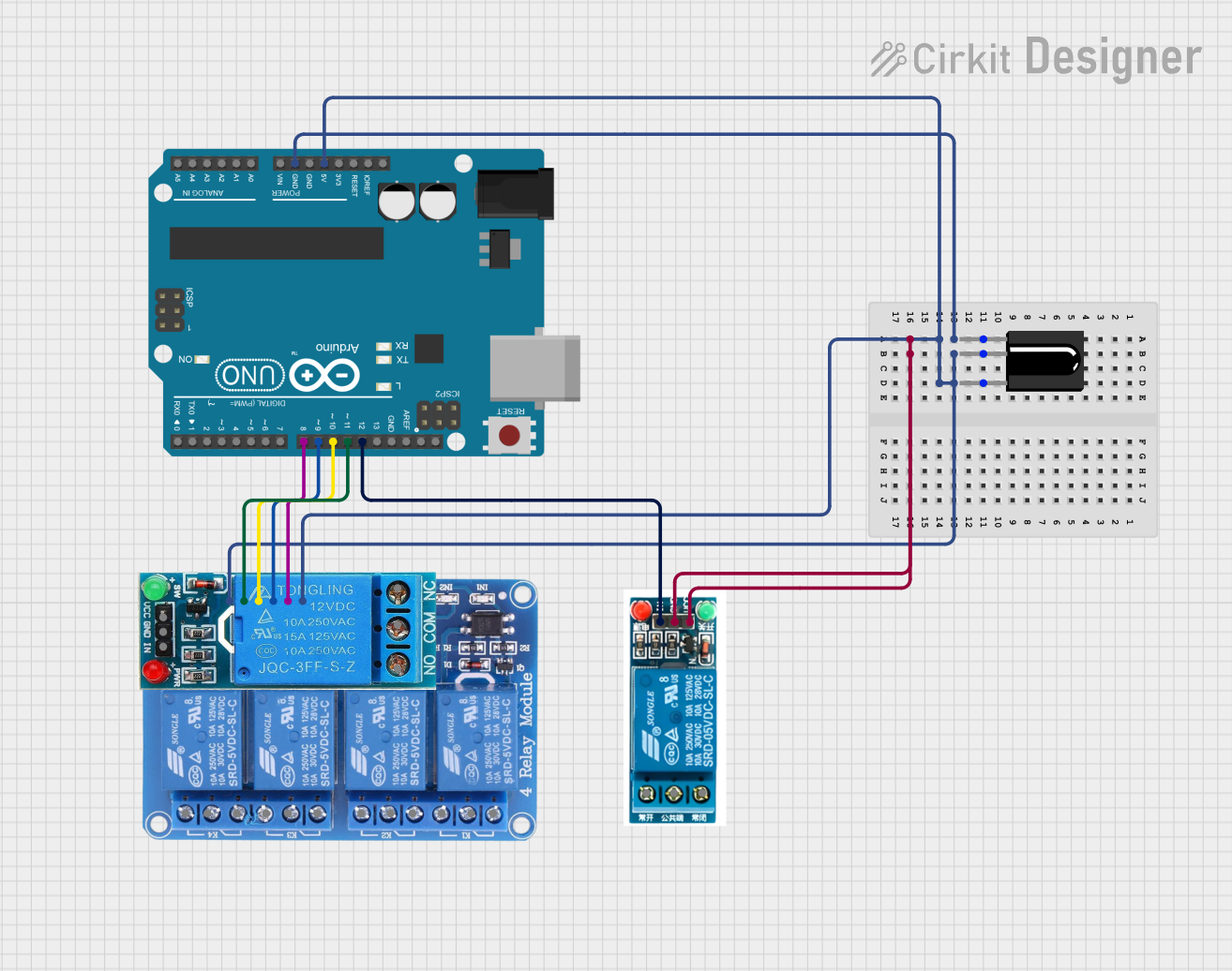
The circuit in question is designed to interface an Arduino UNO with multiple relay modules and an IR receiver. The Arduino UNO is used as the central processing unit, controlling the relay modules based on the input from the IR receiver. The relay modules allow the Arduino to control higher power devices, while the IR receiver enables remote control functionality.
Component List
Arduino UNO
- Description: A microcontroller board based on the ATmega328P.
- Pins: UNUSED, IOREF, Reset, 3.3V, 5V, GND, Vin, A0-A5, SCL, SDA, AREF, D0-D13.
Relay 4 Channel 5v
- Description: A 4-channel relay module for controlling up to four high power devices.
- Pins: GND, IN1-IN4, VCC, COM1-COM4, NO1-NO4, NC1-NC4.
12V SINGLE CHANNEL RELAY
- Description: A single-channel relay capable of controlling one high power device.
- Pins: NC, COM, NO, IN, GND, VCC.
5v relay
- Description: A single-channel 5V relay for controlling one high power device.
- Pins: Normally Open, Common terminal, Normally Closed, In, GND, VCC.
TSOP312 IR Receiver
- Description: An IR receiver module for receiving IR signals from a remote control.
- Pins: GND, Vs, Data.
Wiring Details
Arduino UNO
- 5V connected to Relay 4 Channel 5v VCC.
- GND connected to Relay 4 Channel 5v GND.
- D12 connected to 5v relay In.
- D11 connected to Relay 4 Channel 5v IN4.
- D10 connected to Relay 4 Channel 5v IN3.
- D9 connected to Relay 4 Channel 5v IN2.
- D8 connected to Relay 4 Channel 5v IN1.
Relay 4 Channel 5v
- GND connected to Arduino UNO GND.
- VCC connected to Arduino UNO 5V.
- IN1-IN4 connected to Arduino UNO D8-D11 respectively.
5v relay
- GND connected to Arduino UNO GND.
- VCC connected to Arduino UNO 5V.
- In connected to Arduino UNO D12.
TSOP312 IR Receiver
- GND connected to Arduino UNO GND.
- Vs connected to Arduino UNO 5V.
- Data connected to Arduino UNO D7.
Documented Code
#include <IRremote.h>

// IR Remote HEX codes for buttons
// Button codes are commented next to the corresponding actions

const int RECV_PIN = 7; // IR receiver pin connected to Arduino D7
IRrecv irrecv(RECV_PIN);
decode_results results;

// Relay control pins connected to Arduino D8-D12
#define rly1 8
#define rly2 9
#define rly3 10
#define rly4 11
#define rly5 12

void setup() {
  Serial.begin(9600);
  irrecv.enableIRIn(); // Start the receiver
  irrecv.blink13(true); // Blink the onboard LED with each IR signal received

  // Initialize relay control pins as outputs and set to HIGH (relays OFF)
  pinMode(rly1, OUTPUT);
  pinMode(rly2, OUTPUT);
  pinMode(rly3, OUTPUT);
  pinMode(rly4, OUTPUT);
  pinMode(rly5, OUTPUT);
  digitalWrite(rly1, HIGH);
  digitalWrite(rly2, HIGH);
  digitalWrite(rly3, HIGH);
  digitalWrite(rly4, HIGH);
  digitalWrite(rly5, HIGH);
}

void loop() {
  if (irrecv.decode(&results)) { // Check if an IR signal has been received
    Serial.println(results.value, HEX); // Print the HEX code of the received signal

    // Perform actions based on the received IR signal
    // Each if statement corresponds to a button on the remote
    // The corresponding relay is switched ON, others are OFF
    if (results.value == 0x1FE50AF || results.value == 0x264C7D03) { // Button 1
      digitalWrite(rly1, LOW);
      digitalWrite(rly2, HIGH);
      digitalWrite(rly3, HIGH);
      digitalWrite(rly4, HIGH);
      digitalWrite(rly5, HIGH);
      Serial.println("One Pressed");
    }
    // Additional button actions would be added here following the same pattern

    irrecv.resume(); // Prepare to receive the next IR signal
  }
}
This code is designed to run on the Arduino UNO and uses the IRremote library to decode IR signals from a remote control. The received signals are used to control the state of the relays, allowing for remote operation of connected devices. Each button press on the remote is associated with a specific relay action, toggling the connected device on or off.