
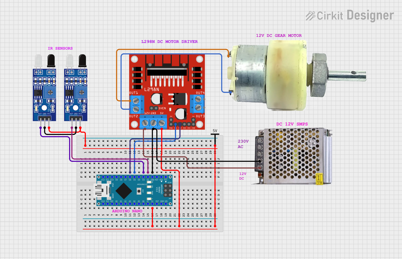
Circuit Documentation
Summary
This circuit is designed to control a 12V geared motor using an Arduino Nano microcontroller and an L298N DC motor driver. The motor's operation is influenced by two FC-51 IR sensors, which likely serve as input devices to trigger motor actions. The circuit is powered by a 12V 5A power supply, which provides the necessary voltage to the motor driver and indirectly to the other components through voltage regulation on the Arduino Nano.
Component List
L298N DC Motor Driver
- Description: A motor driver module capable of driving a pair of DC motors.
- Purpose: To control the direction and speed of the connected 12V geared motor.
- Pins: OUT1, OUT2, 12V, GND, 5V, OUT3, OUT4, 5V-ENA-JMP-I, 5V-ENA-JMP-O, +5V-J1, +5V-J2, ENA, IN1, IN2, IN3, IN4, ENB.
12V Geared Motor
- Description: A DC motor with a gearbox for torque multiplication.
- Purpose: To perform mechanical work as instructed by the motor driver.
- Pins: Terminal 1, Terminal 2.
Sensor FC-51 IR (Two Instances)
- Description: An infrared sensor module with digital output.
- Purpose: To detect obstacles or perform as a proximity switch.
- Pins: OUT, GND, VCC.
Arduino Nano
- Description: A small, complete, and breadboard-friendly microcontroller board based on the ATmega328.
- Purpose: To process sensor inputs and control the motor driver.
- Pins: D1/TX, D0/RX, RESET, GND, D2, D3, D4, D5, D6, D7, D8, D9, D10, D11/MOSI, D12/MISO, VIN, 5V, A7, A6, A5, A4, A3, A2, A1, A0, AREF, 3V3, D13/SCK.
POWER SUPPLY 12V 5AMP
- Description: A power supply unit that converts 220V AC to 12V DC.
- Purpose: To provide power to the motor driver and indirectly to the other components.
- Pins: 220V Positive Pole (AC), 220V Negative Pole (AC), GND, GND (DC), 12V-24V Output (DC).
Vcc (Virtual Component)
- Description: Represents a power source in the circuit.
- Purpose: To symbolize the 5V power rail from the Arduino Nano.
- Pins: Vcc.
Comments (Multiple Instances)
- Description: Non-electrical components used for annotation purposes.
- Purpose: To add notes or comments within the circuit diagram.
Wiring Details
L298N DC Motor Driver
- IN1 connected to Arduino Nano D5
- IN2 connected to Arduino Nano D6
- 5V connected to Arduino Nano 5V, Sensor FC-51 IR VCC (both instances), and Vcc
- GND connected to Arduino Nano GND and POWER SUPPLY 12V 5AMP GND (DC)
- 12V connected to POWER SUPPLY 12V 5AMP 12V-24V Output (DC)
- OUT1 connected to 12V Geared Motor Terminal 1
- OUT2 connected to 12V Geared Motor Terminal 2
12V Geared Motor
- Terminal 1 connected to L298N DC Motor Driver OUT1
- Terminal 2 connected to L298N DC Motor Driver OUT2
Sensor FC-51 IR (Two Instances)
- OUT connected to Arduino Nano D2 and D3 (one sensor to each pin)
- VCC connected to Arduino Nano 5V
- GND connected to each other
Arduino Nano
- D5 connected to L298N DC Motor Driver IN1
- D6 connected to L298N DC Motor Driver IN2
- D2 connected to Sensor FC-51 IR OUT
- D3 connected to Sensor FC-51 IR OUT
- 5V connected to L298N DC Motor Driver 5V, Sensor FC-51 IR VCC (both instances), and Vcc
- GND connected to L298N DC Motor Driver GND and POWER SUPPLY 12V 5AMP GND (DC)
POWER SUPPLY 12V 5AMP
- GND (DC) connected to Arduino Nano GND and L298N DC Motor Driver GND
- 12V-24V Output (DC) connected to L298N DC Motor Driver 12V
Documented Code
Arduino Nano Code (sketch.ino)
void setup() {
  // put your setup code here, to run once:

}

void loop() {
  // put your main code here, to run repeatedly:

}
Note: The provided code is a template and does not contain any functional code. It needs to be populated with instructions to control the motor based on the sensor inputs.