
Arduino Nano Controlled NRF24L01 Wireless Communication Module
View and Edit Project In Cirkit Designer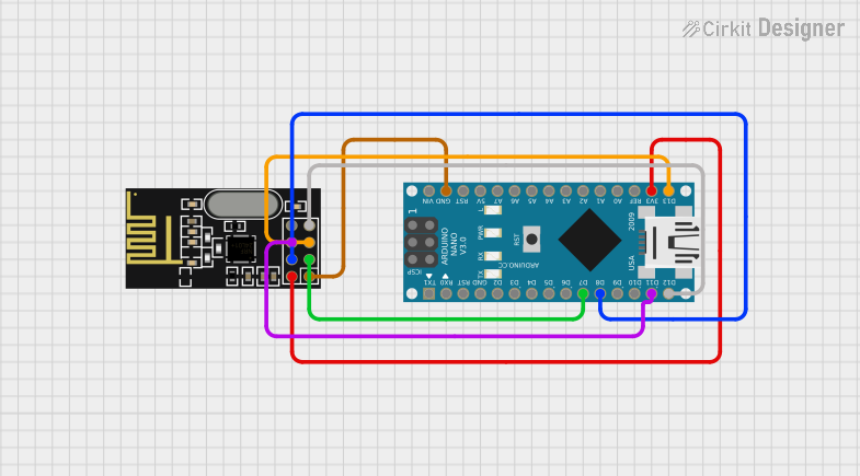
Circuit Documentation
Summary of the Circuit
This circuit integrates an Arduino Nano microcontroller with an NRF24L01 wireless transceiver module. The Arduino Nano serves as the central processing unit, controlling the NRF24L01 module to enable wireless communication capabilities. The NRF24L01 is connected to the Arduino Nano via the SPI (Serial Peripheral Interface) bus, along with control lines for chip enable (CE) and chip select (CSN). The ground (GND) and power (VCC) connections are also established between the two components to provide the necessary power supply for the NRF24L01 module.
Component List
Arduino Nano
- Description: A compact microcontroller board based on the ATmega328P, featuring digital and analog I/O pins.
- Pins: D1/TX, D0/RX, RESET, GND, D2, D3, D4, D5, D6, D7, D8, D9, D10, D11/MOSI, D12/MISO, VIN, 5V, A7, A6, A5, A4, A3, A2, A1, A0, AREF, 3V3, D13/SCK
NRF24L01
- Description: A 2.4GHz wireless transceiver module, commonly used for short-range wireless communication.
- Pins: IRQ (not used), MOSI, CSN, VCC (3V), GND, CE, SCK, MISO
Wiring Details
Arduino Nano
- D7: Connected to NRF24L01 CE
- D8: Connected to NRF24L01 CSN
- D11/MOSI: Connected to NRF24L01 MOSI
- D12/MISO: Connected to NRF24L01 MISO
- GND: Connected to NRF24L01 GND
- 3V3: Connected to NRF24L01 VCC (3V)
- D13/SCK: Connected to NRF24L01 SCK
NRF24L01
- CE: Connected to Arduino Nano D7
- CSN: Connected to Arduino Nano D8
- MOSI: Connected to Arduino Nano D11/MOSI
- MISO: Connected to Arduino Nano D12/MISO
- GND: Connected to Arduino Nano GND
- VCC (3V): Connected to Arduino Nano 3V3
- SCK: Connected to Arduino Nano D13/SCK
Documented Code
Arduino Nano Code (sketch.ino)
void setup() {
  // put your setup code here, to run once:

}

void loop() {
  // put your main code here, to run repeatedly:

}
Additional Notes (documentation.txt)
No additional code documentation was provided for the Arduino Nano.