
Circuit Documentation
Summary
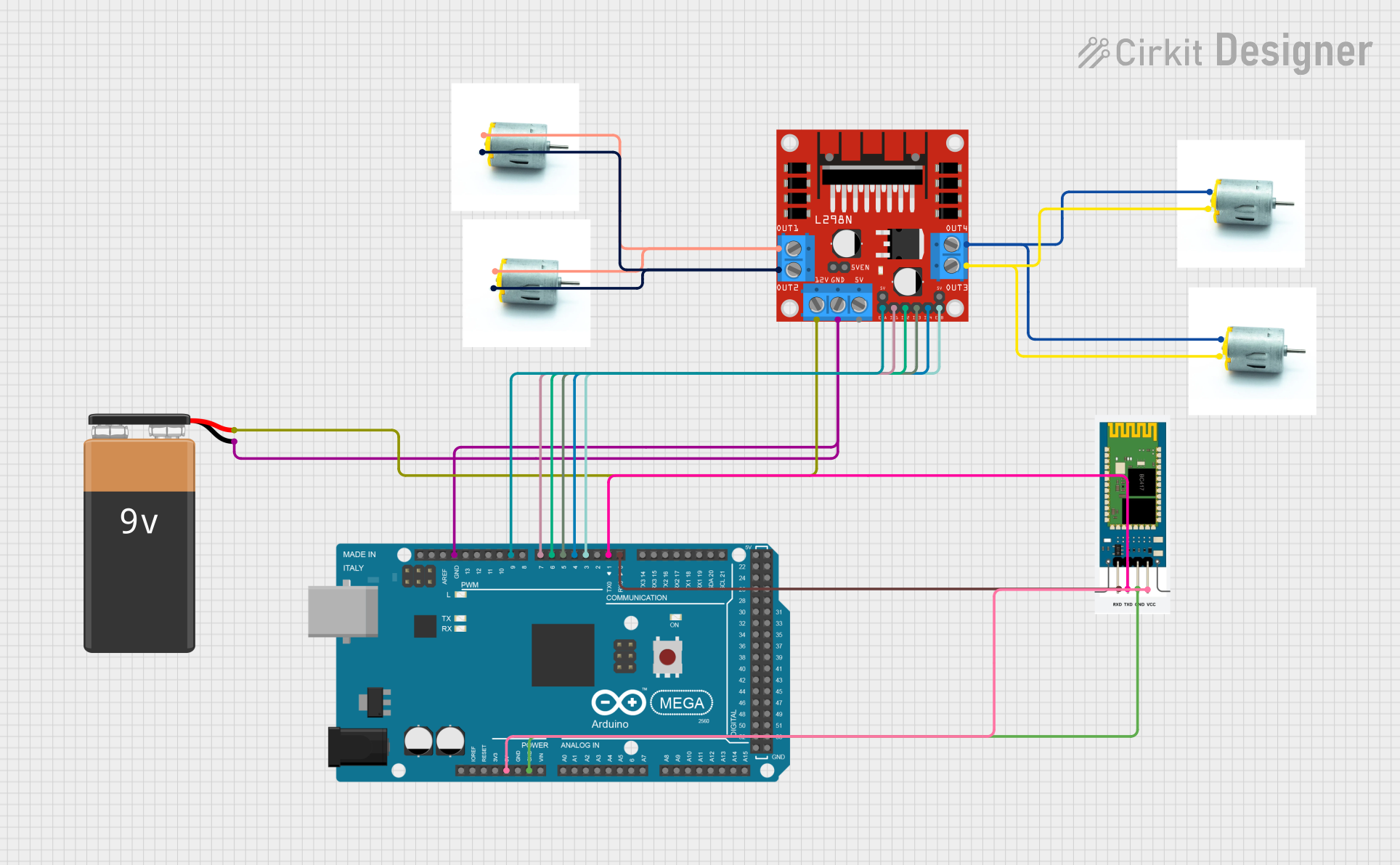
This circuit involves an Arduino Mega 2560 microcontroller, an HC-06 Bluetooth module, an L298N DC motor driver, four DC motors, and a 9V battery. The Arduino Mega 2560 controls the motors via the L298N motor driver, and the HC-06 Bluetooth module allows for wireless communication. The 9V battery powers the motor driver and motors.
Component List
Arduino Mega 2560
- Description: A microcontroller board based on the ATmega2560.
- Pins: IOREF, RESET, 3V3, 5V, GND, VIN, A0-A15, D0-D53, AREF, SDA, SCL
HC-06 Bluetooth Module
- Description: A Bluetooth module for wireless communication.
- Pins: RXD, TXD, GND, VCC
L298N DC Motor Driver
- Description: A dual H-Bridge motor driver.
- Pins: OUT1, OUT2, 12V, GND, 5V, OUT3, OUT4, 5V-ENA-JMP-I, 5V-ENA-JMP-O, +5V-J1, +5V-J2, ENA, IN1, IN2, IN3, IN4, ENB
DC Motor
- Description: A simple DC motor.
- Pins: negative, positive
9V Battery
- Description: A 9V battery for power supply.
- Pins: -, +
Wiring Details
Arduino Mega 2560
- 5V connected to VCC of HC-06 Bluetooth Module
- GND connected to GND of HC-06 Bluetooth Module
- D0 RX0 connected to RXD of HC-06 Bluetooth Module
- D1 TX0 connected to TXD of HC-06 Bluetooth Module
- D3 PWM connected to ENB of L298N DC Motor Driver
- D4 PWM connected to IN4 of L298N DC Motor Driver
- D5 PWM connected to IN3 of L298N DC Motor Driver
- D6 PWM connected to IN2 of L298N DC Motor Driver
- D7 PWM connected to IN1 of L298N DC Motor Driver
- D9 PWM connected to ENA of L298N DC Motor Driver
- GND connected to GND of L298N DC Motor Driver
HC-06 Bluetooth Module
- VCC connected to 5V of Arduino Mega 2560
- GND connected to GND of Arduino Mega 2560
- RXD connected to D0 RX0 of Arduino Mega 2560
- TXD connected to D1 TX0 of Arduino Mega 2560
L298N DC Motor Driver
- ENB connected to D3 PWM of Arduino Mega 2560
- IN4 connected to D4 PWM of Arduino Mega 2560
- IN3 connected to D5 PWM of Arduino Mega 2560
- IN2 connected to D6 PWM of Arduino Mega 2560
- IN1 connected to D7 PWM of Arduino Mega 2560
- ENA connected to D9 PWM of Arduino Mega 2560
- GND connected to GND of Arduino Mega 2560 and - of 9V Battery
- 12V connected to + of 9V Battery
- OUT1 connected to negative of two DC Motors
- OUT2 connected to positive of two DC Motors
- OUT3 connected to positive of two DC Motors
- OUT4 connected to negative of two DC Motors
DC Motors
- negative of two DC Motors connected to OUT1 of L298N DC Motor Driver
- positive of two DC Motors connected to OUT2 of L298N DC Motor Driver
- negative of two DC Motors connected to OUT4 of L298N DC Motor Driver
- positive of two DC Motors connected to OUT3 of L298N DC Motor Driver
9V Battery
- - connected to GND of L298N DC Motor Driver and GND of Arduino Mega 2560
- + connected to 12V of L298N DC Motor Driver
Code Documentation
const int motorA1  = 5;
const int motorA2  = 7;
const int motorB1  = 6;
const int motorB2  = 4;
int i=0;
int j=0;
int state;
int vSpeed=255;

void setup() {
    pinMode(motorA1, OUTPUT);
    pinMode(motorA2, OUTPUT);
    pinMode(motorB1, OUTPUT);
    pinMode(motorB2, OUTPUT);
    Serial.begin(9600);
}

void loop() {
    if(Serial.available() > 0){
      state = Serial.read();
    }

    if (state == '0'){
      vSpeed=0;
    } else if (state == '1'){
      vSpeed=100;
    } else if (state == '2'){
      vSpeed=180;
    } else if (state == '3'){
      vSpeed=200;
    } else if (state == '4'){
      vSpeed=255;
    }

    if (state == 'F') {
      analogWrite(motorA1, vSpeed);
      analogWrite(motorA2, 0);
      analogWrite(motorB1, vSpeed);
      analogWrite(motorB2, 0);
    } else if (state == 'A') {
      analogWrite(motorA1,vSpeed );
      analogWrite(motorA2, 0);
      analogWrite(motorB1, 100);
      analogWrite(motorB2, 0);
    } else if (state == 'B') {
      analogWrite(motorA1, 100);
      analogWrite(motorA2, 0);
      analogWrite(motorB1, vSpeed);
      analogWrite(motorB2, 0);
    } else if (state == 'C') {
      analogWrite(motorA1, 0);
      analogWrite(motorA2, vSpeed);
      analogWrite(motorB1, 0);
      analogWrite(motorB2, vSpeed);
    } else if (state == 'D') {
      analogWrite(motorA1, 0);
      analogWrite(motorA2, 100);
      analogWrite(motorB1, 0);
      analogWrite(motorB2, vSpeed);
    } else if (state == 'F') {
      analogWrite(motorA1, vSpeed);
      analogWrite(motorA2, 150);
      analogWrite(motorB1, 0);
      analogWrite(motorB2, 0);
    } else if (state == 'G') {
      analogWrite(motorA1, 0);
      analogWrite(motorA2, 0);
      analogWrite(motorB1, vSpeed);
      analogWrite(motorB2, 150);
    } else if (state == 'H'){
      analogWrite(motorA1, 0);
      analogWrite(motorA2, 0);
      analogWrite(motorB1, 0);
      analogWrite(motorB2, 0);
    }
}
This code is for the Arduino Mega 2560 microcontroller. It sets up the pins for controlling the motors and reads commands from the serial input to control the speed and direction of the motors. The setup function initializes the pins and the serial communication. The loop function continuously checks for serial input and adjusts the motor speeds and directions based on the received commands.