
Arduino UNO-Based Environmental Monitoring System with Multiple Sensors
View and Edit Project In Cirkit Designer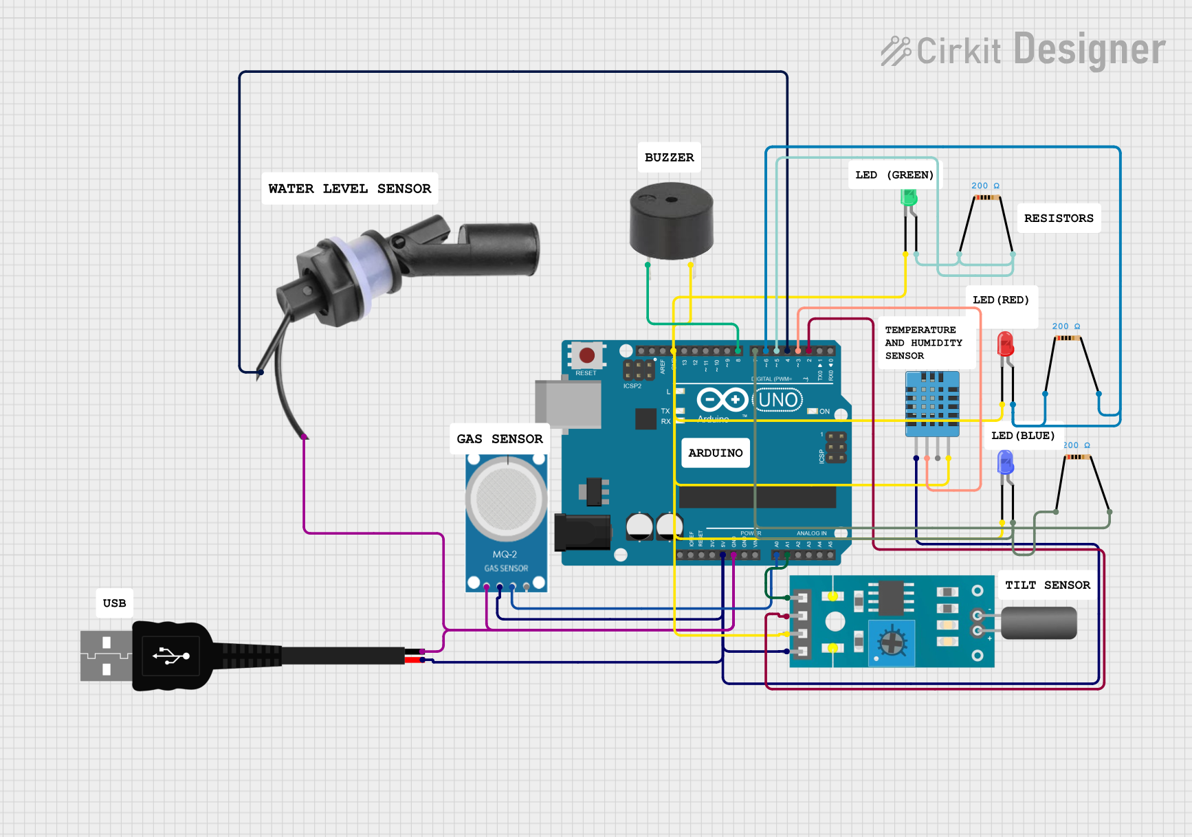
Circuit Documentation
Summary
This document provides a detailed overview of a circuit that includes an Arduino UNO microcontroller, various sensors (MQ-2, Tilt sensor, DHT11 Humidity and Temperature Sensor, Water Level Float Switch Sensor), LEDs, resistors, a buzzer, and a USB male 2-pin connection. The circuit is designed to interface with these components to perform various sensing and output tasks.
Component List
Arduino UNO
- Description: A microcontroller board based on the ATmega328P.
- Pins: UNUSED, IOREF, Reset, 3.3V, 5V, GND, Vin, A0, A1, A2, A3, A4, A5, SCL, SDA, AREF, D13, D12, D11, D10, D9, D8, D7, D6, D5, D4, D3, D2, D1, D0
MQ-2
- Description: Gas sensor for detecting LPG, i-butane, propane, methane, alcohol, Hydrogen, and smoke.
- Pins: GND, VCC, ANALOG, Digital
Tilt Sensor
- Description: A sensor that detects orientation or tilt.
- Pins: A0, D0, GND, VCC
DHT11 Humidity and Temperature Sensor
- Description: A sensor for measuring temperature and humidity.
- Pins: VDD, DATA, NULL, GND
Resistor
- Description: A passive electrical component that implements electrical resistance.
- Pins: pin1, pin2
- Properties: Resistance: 200 Ohms
LED: Two Pin (red)
- Description: A red light-emitting diode.
- Pins: cathode, anode
LED: Two Pin (blue)
- Description: A blue light-emitting diode.
- Pins: cathode, anode
LED: Two Pin (green)
- Description: A green light-emitting diode.
- Pins: cathode, anode
Water Level Float Switch Sensor
- Description: A sensor that detects the presence of water at a certain level.
- Pins: Wire2, Wire1
Buzzer
- Description: An audio signaling device.
- Pins: PIN, GND
USB Male 2 Pin Connection
- Description: A USB connector for power supply.
- Pins: Negative -, Positive +
Wiring Details
Arduino UNO
- 5V: Connected to VCC of MQ-2, VCC of Tilt sensor, VDD of DHT11 Humidity and Temperature Sensor, and Positive + of USB male 2 pin connection.
- GND: Connected to GND of MQ-2, GND of Tilt sensor, GND of DHT11 Humidity and Temperature Sensor, Negative - of USB male 2 pin connection, cathode of LED (red), cathode of LED (blue), cathode of LED (green), and GND of buzzer.
- A0: Connected to ANALOG of MQ-2.
- A1: Connected to A0 of Tilt sensor.
- D8: Connected to PIN of buzzer.
- D7: Connected to pin2 of Resistor, which is connected to pin1 of Resistor, which is connected to anode of LED (blue).
- D6: Connected to pin2 of Resistor, which is connected to pin1 of Resistor, which is connected to anode of LED (red).
- D5: Connected to pin2 of Resistor, which is connected to pin1 of Resistor, which is connected to anode of LED (green).
- D4: Connected to Wire1 of Water Level Float Switch Sensor.
- D3: Connected to DATA of DHT11 Humidity and Temperature Sensor.
- D2: Connected to D0 of Tilt sensor.
MQ-2
- VCC: Connected to 5V of Arduino UNO.
- GND: Connected to GND of Arduino UNO.
- ANALOG: Connected to A0 of Arduino UNO.
Tilt Sensor
- VCC: Connected to 5V of Arduino UNO.
- GND: Connected to GND of Arduino UNO.
- A0: Connected to A1 of Arduino UNO.
- D0: Connected to D2 of Arduino UNO.
DHT11 Humidity and Temperature Sensor
- VDD: Connected to 5V of Arduino UNO.
- GND: Connected to GND of Arduino UNO.
- DATA: Connected to D3 of Arduino UNO.
Resistor
- pin1: Connected to pin2 of Resistor, which is connected to D7 of Arduino UNO, and anode of LED (blue).
- pin1: Connected to pin2 of Resistor, which is connected to D6 of Arduino UNO, and anode of LED (red).
- pin1: Connected to pin2 of Resistor, which is connected to D5 of Arduino UNO, and anode of LED (green).
LED: Two Pin (red)
- cathode: Connected to GND of Arduino UNO.
- anode: Connected to pin2 of Resistor, which is connected to D6 of Arduino UNO.
LED: Two Pin (blue)
- cathode: Connected to GND of Arduino UNO.
- anode: Connected to pin2 of Resistor, which is connected to D7 of Arduino UNO.
LED: Two Pin (green)
- cathode: Connected to GND of Arduino UNO.
- anode: Connected to pin2 of Resistor, which is connected to D5 of Arduino UNO.
Water Level Float Switch Sensor
- Wire2: Connected to Negative - of USB male 2 pin connection.
- Wire1: Connected to D4 of Arduino UNO.
Buzzer
- PIN: Connected to D8 of Arduino UNO.
- GND: Connected to GND of Arduino UNO.
USB Male 2 Pin Connection
- Positive +: Connected to 5V of Arduino UNO.
- Negative -: Connected to GND of Arduino UNO.
Code Documentation
Arduino UNO Code
sketch.ino
void setup() {
  // put your setup code here, to run once:

}

void loop() {
  // put your main code here, to run repeatedly:

}
documentation.txt
This document provides a comprehensive overview of the circuit, including a summary, component list, wiring details, and code documentation. Each component is described, and its connections are detailed to ensure clarity and ease of understanding.