
Circuit Documentation
Summary of the Circuit
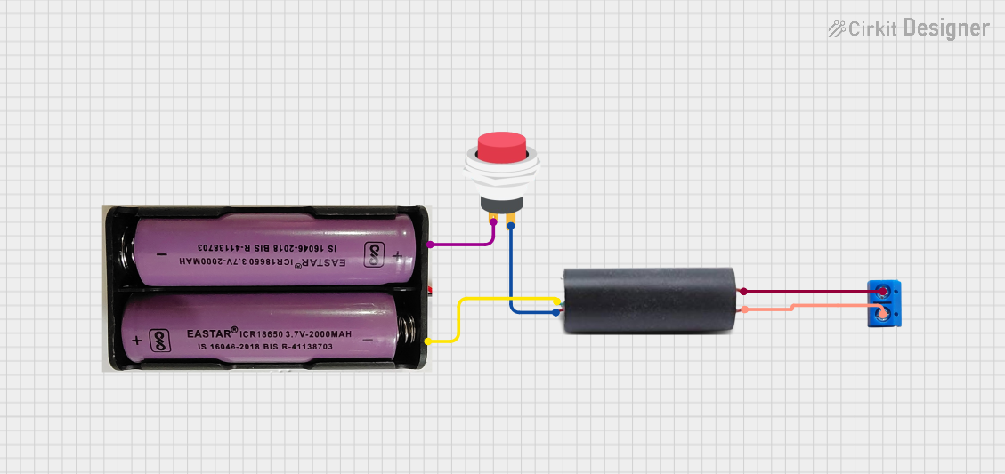
This circuit appears to be designed to control a high voltage generator using a 7.4V power source and a push switch. The high voltage generator is connected to a terminal PCB for output, and its operation is controlled by the push switch. The 7.4V power source provides the necessary power to the high voltage generator, with the push switch acting as an on/off control. The ground of the high voltage generator is connected to the negative terminal of the power source to complete the circuit.
Component List
High Voltage Generator
- Pins: out 1, Out 2, VCC, GND
- Description: A device that steps up the input voltage to a higher output voltage.
- Purpose: To generate a high voltage output from a lower voltage input.
7.4V Battery
- Pins: +, -
- Description: A power source providing a nominal voltage of 7.4V.
- Purpose: To supply power to the high voltage generator.
2Pin Push Switch
- Pins: Input +, Output +
- Description: A switch that allows current to flow when pressed.
- Purpose: To control the power supply to the high voltage generator.
Terminal PCB 2 Pin
- Pins: Pin A, Pin B
- Description: A simple two-pin terminal for connecting external components.
- Purpose: To provide connection points for the high voltage output.
Wiring Details
High Voltage Generator
- out 1 connected to Terminal PCB 2 Pin Pin A
- Out 2 connected to Terminal PCB 2 Pin Pin B
- VCC connected to 2Pin Push Switch Output +
- GND connected to 7.4V Battery -
7.4V Battery
- + connected to 2Pin Push Switch Input +
- - connected to High Voltage Generator GND
2Pin Push Switch
- Input + connected to 7.4V Battery +
- Output + connected to High Voltage Generator VCC
Terminal PCB 2 Pin
- Pin A connected to High Voltage Generator out 1
- Pin B connected to High Voltage Generator Out 2
Documented Code
No microcontroller code has been provided for this circuit. If the circuit is later updated to include a microcontroller for additional control or monitoring, the code will be documented in this section.