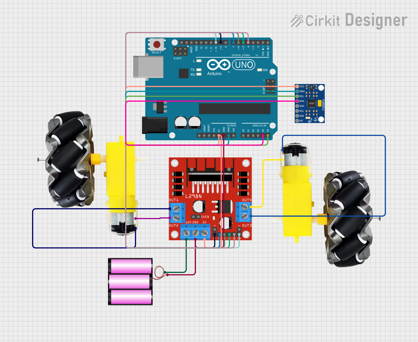
Arduino-Controlled Robotic Vehicle with MPU6050 Gyroscope

Circuit Documentation
Summary of the Circuit
This circuit is designed to interface an Arduino UNO with an InvenSense MPU6050 motion sensor and control a pair of motors using an L298N DC motor driver. The motors are powered by a 12V battery, and the Arduino UNO is used as the central processing unit to handle sensor data and motor control logic. The MPU6050 provides acceleration and gyroscope readings to the Arduino, which then processes this information to control the speed and direction of the motors through the L298N driver.
Component List
Arduino UNO
- Microcontroller board based on the ATmega328P
- Provides I/O pins for interfacing with various sensors and modules
- Operates at 5V and can be powered via USB or an external power supply
Motor and Wheels (x2)
- DC motors attached to wheels for mobility
- Requires a power supply and control signals to operate
L298N DC Motor Driver
- Dual H-bridge motor driver capable of driving two DC motors
- Operates at up to 12V and provides pins for motor control inputs and power supply
Battery 12V
- Provides the power source for the motors and the motor driver
- Typically a lead-acid or lithium-ion battery capable of delivering sufficient current for motor operation
InvenSense MPU6050
- A motion tracking device that includes a 3-axis gyroscope and a 3-axis accelerometer
- Communicates with the Arduino UNO via I2C protocol
Wiring Details
Arduino UNO
5Vconnected to MPU6050VCCand L298N5VGNDconnected to 12V Battery-, MPU6050GND, and L298NGNDA4 (SDA)connected to MPU6050SDAA5 (SCL)connected to MPU6050SCLD10connected to L298NENBD9connected to L298NENAD7connected to L298NIN1D6connected to L298NIN2D5connected to L298NIN3D4connected to L298NIN4
Motor and Wheels
- First motor
vccconnected to L298NOUT3 - First motor
GNDconnected to L298NOUT4 - Second motor
vccconnected to L298NOUT1 - Second motor
GNDconnected to L298NOUT2
L298N DC Motor Driver
12Vconnected to 12V Battery+- Motor control inputs (
ENA,ENB,IN1,IN2,IN3,IN4) connected to corresponding Arduino UNO pins
Battery 12V
+connected to L298N12V-connected to Arduino UNOGND
InvenSense MPU6050
VCCconnected to Arduino UNO5VGNDconnected to Arduino UNOGNDSDAconnected to Arduino UNOA4 (SDA)SCLconnected to Arduino UNOA5 (SCL)
Documented Code
Arduino UNO Code (sketch.ino)
void setup() {
  // put your setup code here, to run once:

}

void loop() {
  // put your main code here, to run repeatedly:

}
This code is a template for the Arduino UNO. The setup() function is intended to contain initialization code that runs once when the microcontroller is powered on or reset. The loop() function is designed to contain the main logic of the program, which will be executed repeatedly as long as the Arduino is powered.
The actual implementation of the code will depend on the specific requirements of the application, such as reading sensor data from the MPU6050 and controlling the motors via the L298N motor driver.