
Arduino UNO Power Monitor with LCD Display and Wi-Fi Connectivity
View and Edit Project In Cirkit Designer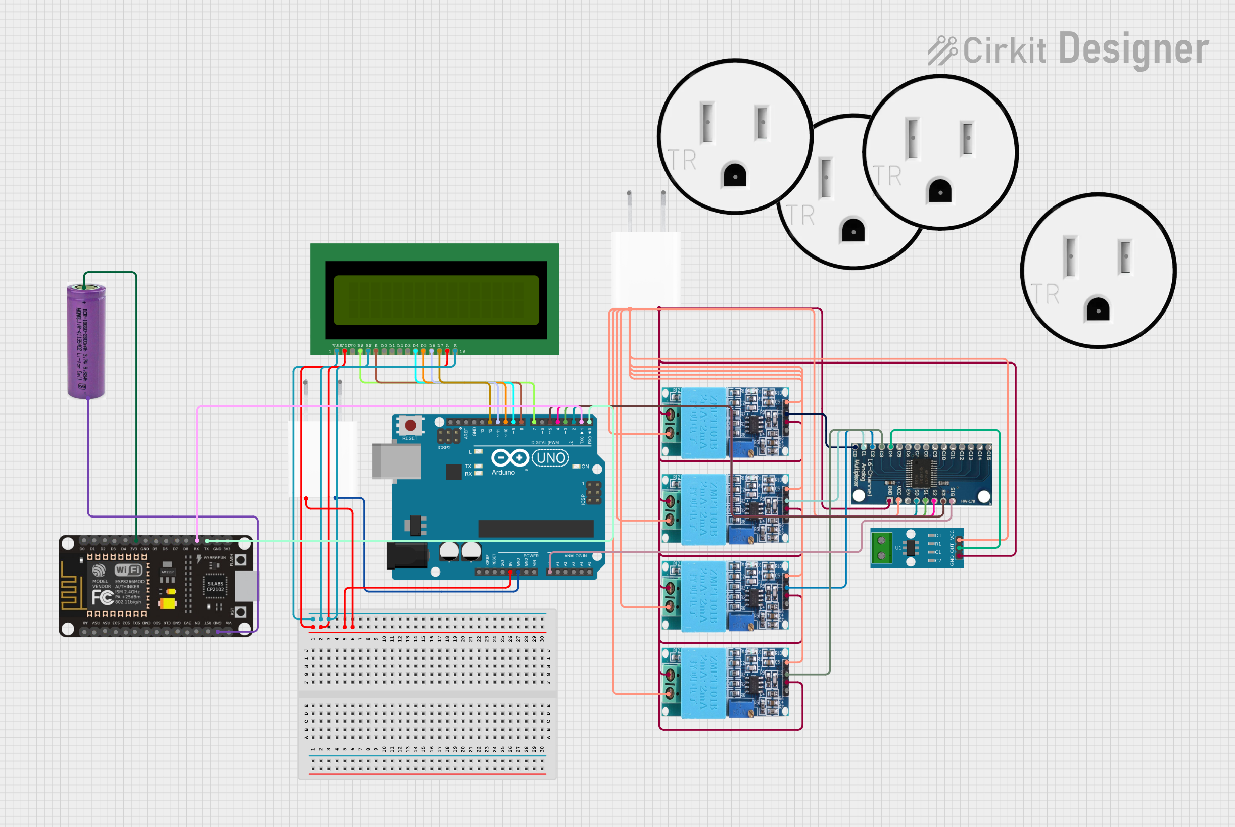
Circuit Documentation
Summary
This circuit is designed to monitor the wattage of an appliance using various sensors. The main components include an Arduino UNO, an LCD 16x2 display, ACS712 current sensor, ZMPT101B voltage sensors, a 16-channel analog multiplexer, and an ESP8266 NodeMCU. The circuit reads voltage and current values, calculates power, and displays it on the LCD. It also sends data to the ESP8266 for further processing.
Component List
LCD 16x2 (Wokwi Compatible)
- Description: A 16x2 character LCD display.
- Pins: VSS, VDD, V0, RS, RW, E, D0, D1, D2, D3, D4, D5, D6, D7, A, K
ACS712 Current Sensor 5A 20A 30A
- Description: A current sensor capable of measuring up to 30A.
- Pins: 1, 2, GND, OUT, VCC
ZMPT101B
- Description: A voltage sensor module.
- Pins: OUT, GND, VCC, NEUTRO, FASE
Arduino UNO
- Description: A microcontroller board based on the ATmega328P.
- Pins: UNUSED, IOREF, Reset, 3.3V, 5V, GND, Vin, A0, A1, A2, A3, A4, A5, SCL, SDA, AREF, D13, D12, D11, D10, D9, D8, D7, D6, D5, D4, D3, D2, D1, D0
5V Adapter
- Description: A power adapter providing 5V output.
- Pins: AC In 1, AC In 2, 5V, GND
16 Channel Analog Multiplexer
- Description: A multiplexer for selecting one of 16 analog input channels.
- Pins: GND, VCC, EN, S0, S1, S2, S3, SIG, C0, C1, C2, C3, C4, C5, C6, C7, C8, C9, C10, C11, C12, C13, C14, C15
3.3V Battery
- Description: A battery providing 3.3V output.
- Pins: +, -
120V Outlet
- Description: A standard 120V AC outlet.
- Pins: AC Neutral, AC Hot, GND
ESP8266 NodeMCU
- Description: A Wi-Fi module based on the ESP8266.
- Pins: D0, D1, D2, D3, D4, 3V3, GND, D5, D6, D7, D8, RX, TX, A0, RSV, SD3, SD2, SD1, CMD, SD0, CLK, EN, RST, VIN
Wiring Details
LCD 16x2 (Wokwi Compatible)
- VSS, RW, K: Connected together.
- VDD, A: Connected to 5V from Arduino UNO and 5V Adapter.
- RS: Connected to D7 on Arduino UNO.
- E: Connected to D8 on Arduino UNO.
- D4: Connected to D9 on Arduino UNO.
- D5: Connected to D10 on Arduino UNO.
- D6: Connected to D11 on Arduino UNO.
- D7: Connected to D12 on Arduino UNO.
ACS712 Current Sensor 5A 20A 30A
- GND: Connected to GND of 5V Adapter.
- OUT: Connected to C4 of 16 Channel Analog Multiplexer.
- VCC: Connected to 5V of 5V Adapter.
ZMPT101B (4 Instances)
- GND, NEUTRO: Connected together and to GND of 5V Adapter.
- VCC, FASE: Connected together and to 5V of 5V Adapter.
- OUT:
- Instance 1: Connected to C0 of 16 Channel Analog Multiplexer.
- Instance 2: Connected to C1 of 16 Channel Analog Multiplexer.
- Instance 3: Connected to C2 of 16 Channel Analog Multiplexer.
- Instance 4: Connected to C3 of 16 Channel Analog Multiplexer.
Arduino UNO
- 5V: Connected to 5V of 5V Adapter.
- GND: Connected to GND of 5V Adapter.
- D2: Connected to S0 of 16 Channel Analog Multiplexer.
- D3: Connected to S1 of 16 Channel Analog Multiplexer.
- D4: Connected to S2 of 16 Channel Analog Multiplexer.
- D5: Connected to S3 of 16 Channel Analog Multiplexer.
- A0: Connected to SIG of 16 Channel Analog Multiplexer.
- D1: Connected to RX of ESP8266 NodeMCU.
- D0: Connected to TX of ESP8266 NodeMCU.
5V Adapter
- 5V: Connected to VDD and A of LCD 16x2, VCC of ACS712 Current Sensor, and VCC of ZMPT101B sensors.
- GND: Connected to GND of Arduino UNO, GND and NEUTRO of ZMPT101B sensors, and GND of ACS712 Current Sensor.
16 Channel Analog Multiplexer
- GND: Connected to GND of 5V Adapter.
- VCC: Connected to 5V of 5V Adapter.
- S0, S1, S2, S3: Connected to D2, D3, D4, D5 of Arduino UNO respectively.
- SIG: Connected to A0 of Arduino UNO.
- C0, C1, C2, C3, C4: Connected to OUT of ZMPT101B sensors and OUT of ACS712 Current Sensor.
ESP8266 NodeMCU
- RX: Connected to D1 of Arduino UNO.
- TX: Connected to D0 of Arduino UNO.
- 3V3: Connected to + of 3.3V Battery.
- GND: Connected to - of 3.3V Battery.
Code Documentation
/*
 * Arduino Sketch to monitor the wattage of an appliance using various sensors.
 * Components:
 * - Arduino UNO
 * - LCD 16x2
 * - ACS712 Current Sensor
 * - ZMPT101B Voltage Sensors
 * - 16 Channel Analog Multiplexer
 * - ESP8266 NodeMCU
 *
 * The code reads voltage and current values, calculates power, and displays it
 * on the LCD. It also sends data to the ESP8266 for further processing.
 */

#include <LiquidCrystal.h>

// LCD pin configuration
const int rs = 7, en = 8, d4 = 9, d5 = 10, d6 = 11, d7 = 12;
LiquidCrystal lcd(rs, en, d4, d5, d6, d7);

// Multiplexer pin configuration
const int S0 = 2, S1 = 3, S2 = 4, S3 = 5;
const int SIG = A0;

// Current sensor pin
const int currentSensorPin = 4; // Connected to C4 of multiplexer

// Voltage sensor pins
const int voltageSensorPins[] = {0, 1, 2, 3}; // Connected to C0-C3 of multiplexer

void setup() {
  // Initialize LCD
  lcd.begin(16, 2);
  lcd.print("Power Monitor");

  // Initialize multiplexer control pins
  pinMode(S0, OUTPUT);
  pinMode(S1, OUTPUT);
  pinMode(S2, OUTPUT);
  pinMode(S3, OUTPUT);

  // Initialize serial communication
  Serial.begin(9600);
}

void loop() {
  float voltage = readVoltage();
  float current = readCurrent();
  float power = voltage * current;

  // Display power on LCD
  lcd.setCursor(0, 1);
  lcd.print("Power: ");
  lcd.print(power);
  lcd.print(" W");

  // Send data to ESP8266
  Serial.print("Voltage: ");
  Serial.print(voltage);
  Serial.print(" V, Current: ");
  Serial.print(current);
  Serial.print(" A, Power: ");
  Serial.print(power);
  Serial.println(" W");

  delay(1000); // Update every second
}

float readVoltage() {
  float voltageSum = 0;
  for (int i = 0; i < 4; i++) {
    selectMultiplexerChannel(i);
    voltageSum += analogRead(SIG);
  }
  return (voltageSum / 4) * (5