
ESP32-Based Environmental Monitoring and Response System with Fire Safety
View and Edit Project In Cirkit Designer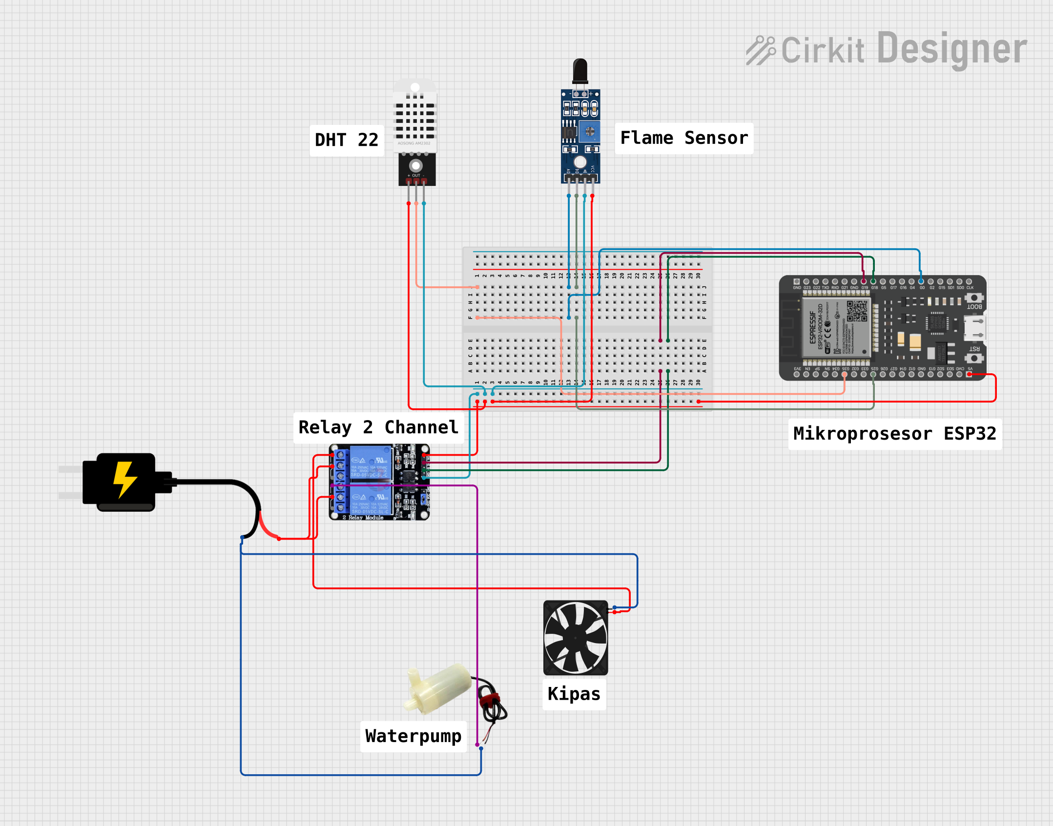
Circuit Documentation
Summary of the Circuit
This circuit is designed to interface an ESP32 microcontroller with a variety of sensors and actuators. The ESP32 reads data from a DHT22 temperature and humidity sensor and an SHT113 flame sensor. It controls a 5V mini water pump and a fan through a two-channel relay module. The power for the circuit is provided by a DC Source of 5V. The ESP32 is the central processing unit of the circuit, responsible for reading sensor data, processing it, and controlling the actuators based on predefined conditions.
Component List
ESP32 - 38 pins
- Description: A microcontroller with Wi-Fi and Bluetooth capabilities, featuring a wide range of GPIO pins.
- Pins: 3V3, EN, SP, SN, G34, G35, G32, G33, G25, G26, G27, G14, G12, GND, G13, SD2, SD3, CMD, 5V, G23, G22, TXD, RXD, G21, G19, G18, G5, G17, G16, G4, G0, G2, G15, SD1, SD0, CLK
5V Mini Water Pump
- Description: A small pump that operates at 5V for pumping water.
- Pins: Positive pin, Negative pin
Fan
- Description: A 5V fan used for cooling purposes.
- Pins: GND, 5V
DHT22
- Description: A sensor for measuring temperature and humidity.
- Pins: +, Out, -
Sensor SHT113 Flame
- Description: A flame sensor capable of detecting fire sources.
- Pins: A0, D0, GND, VCC
Two Channel Relay 5V
- Description: A relay module with two channels that can control high power devices.
- Pins: VCC, IN2, IN1, GND, NC2, C2, NO2, NC1, C1, NO1
DC Source 5V
- Description: A power supply that provides a 5V output.
- Pins: VCC, GND
Wiring Details
ESP32 - 38 pins
- G35 connected to DHT22 Out
- G0 connected to Sensor SHT113 Flame A0
- G25 connected to Sensor SHT113 Flame D0
- G19 connected to Two Channel Relay 5V IN2
- G18 connected to Two Channel Relay 5V IN1
- 5V connected to Two Channel Relay 5V VCC, DHT22 +, Sensor SHT113 Flame VCC
5V Mini Water Pump
- Positive pin connected to Two Channel Relay 5V NC1
- Negative pin connected to DC Source 5V GND
Fan
- GND connected to DC Source 5V GND
- 5V connected to Two Channel Relay 5V NC2
DHT22
-
- connected to ESP32 5V
- Out connected to ESP32 G35
-
- connected to Two Channel Relay 5V GND
Sensor SHT113 Flame
- A0 connected to ESP32 G0
- D0 connected to ESP32 G25
- GND connected to Two Channel Relay 5V GND
- VCC connected to ESP32 5V
Two Channel Relay 5V
- VCC connected to ESP32 5V
- IN2 connected to ESP32 G19
- IN1 connected to ESP32 G18
- GND connected to DHT22 -, Sensor SHT113 Flame GND
- NC1 connected to 5V Mini Water Pump Positive pin
- NC2 connected to Fan 5V
- C1, C2 connected to DC Source 5V VCC
DC Source 5V
- VCC connected to Two Channel Relay 5V C1, C2
- GND connected to 5V Mini Water Pump Negative pin, Fan GND
Documented Code
Since no code was provided, this section is left blank. The code for the ESP32 would typically include initialization of the GPIO pins, setup of the Wi-Fi or Bluetooth modules if needed, reading data from the DHT22 and SHT113 sensors, and controlling the relay module to turn on or off the water pump and fan based on sensor readings or other logic.