
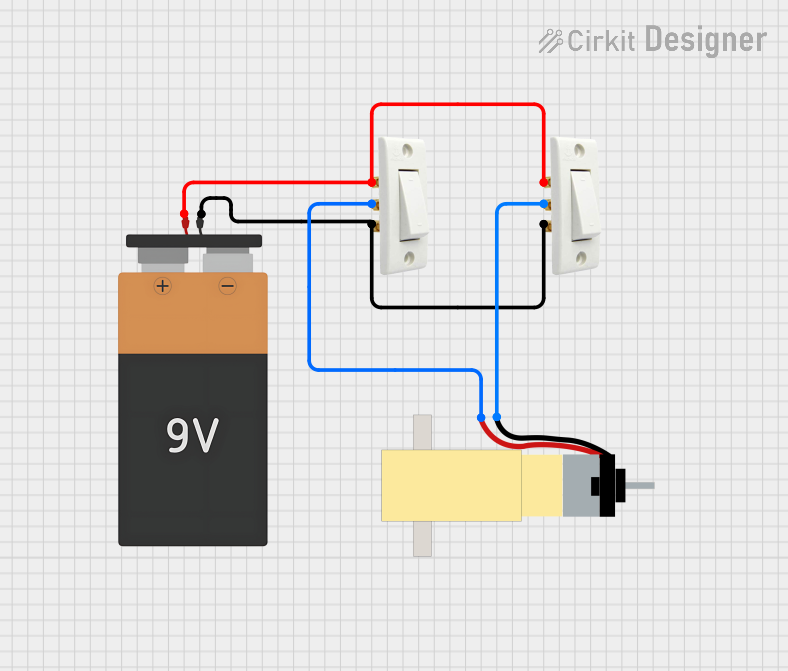
Circuit Documentation
Summary of the Circuit
This circuit consists of two 2-way switches, a 9V battery, and a hobby gearmotor with a 48:1 gearbox. The switches are used to control the power supplied from the battery to the gearmotor. When the switches are toggled, they either complete or break the circuit, thus controlling the operation of the gearmotor.
Component List
2 Way Switch
- Description: A switch with three terminals that can be used to switch the current between two different paths.
- Pins:
t1,t2,t3 - Purpose: To control the electrical connection between the battery and the gearmotor.
Battery 9V
- Description: A standard 9-volt battery used as the power source for the circuit.
- Pins:
VCC,GND - Purpose: To provide the necessary voltage and current to power the gearmotor.
Hobby Gearmotor with 48:1 Gearbox
- Description: A small DC motor with a gearbox that reduces the output speed while increasing torque.
- Pins:
pin 1,pin 2 - Purpose: To perform mechanical work when powered by the battery.
Wiring Details
2 Way Switch
- Pins:
t1: Connected to thet1of the other 2-way switch andVCCof the battery.t2: Connected topin 2of the gearmotor.t3: Connected to thet3of the other 2-way switch andGNDof the battery.
Battery 9V
- Pins:
VCC: Connected tot1of both 2-way switches.GND: Connected tot3of both 2-way switches.
Hobby Gearmotor with 48:1 Gearbox
- Pins:
pin 1: Connected tot2of one of the 2-way switches.pin 2: Connected tot2of the other 2-way switch.
Documented Code
There is no microcontroller or embedded code associated with this circuit as per the provided inputs. Therefore, this section is not applicable to the current documentation.
This documentation provides an overview of the circuit's components, their purpose, and how they are wired together. It should serve as a guide for understanding and replicating the circuit.