
ESP32 and L298N Motor Driver-Based Wi-Fi Controlled Robotic Car with IR Sensors
View and Edit Project In Cirkit Designer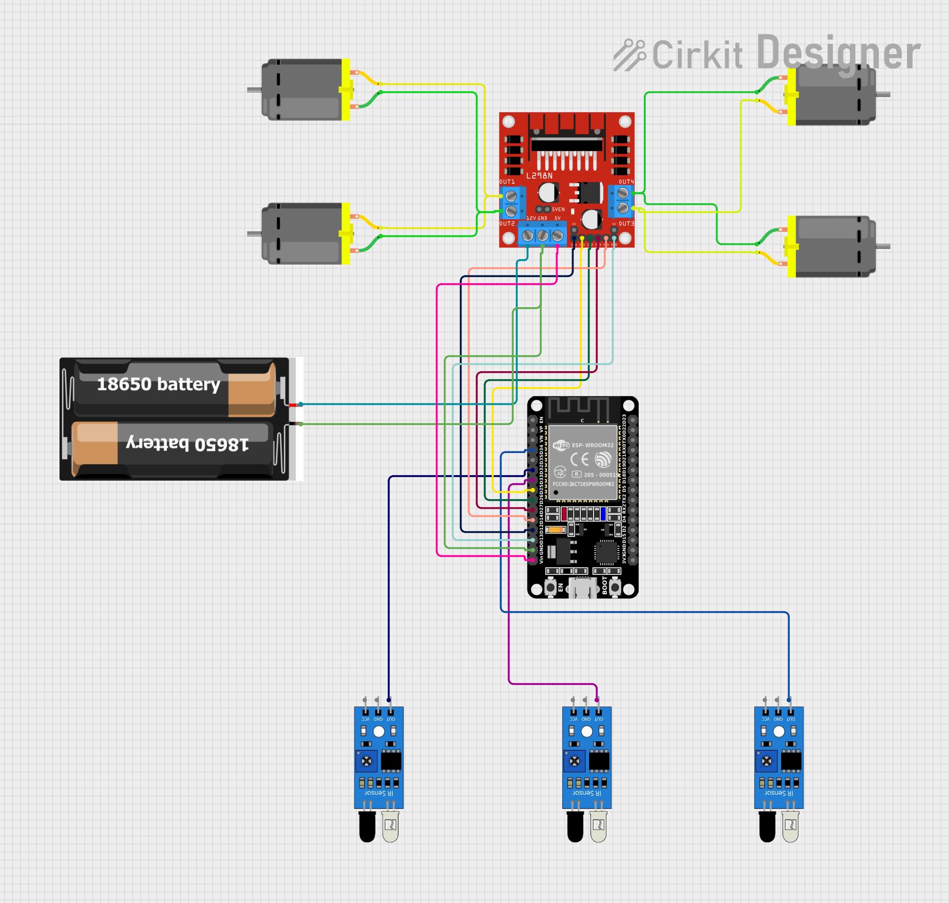
Circuit Documentation
Summary
This document provides a detailed overview of a circuit that includes an ESP32 microcontroller, multiple IR sensors, a DC motor driver (L298N), several DC motors, and a 2x 18650 battery pack. The circuit is designed to interface the IR sensors with the ESP32, control the DC motors via the L298N motor driver, and power the entire setup using the battery pack.
Component List
IR Sensor
- Description: Infrared sensor used for detecting obstacles or line following.
- Pins: out, gnd, vcc
L298N DC Motor Driver
- Description: Dual H-Bridge motor driver used to control the speed and direction of DC motors.
- Pins: OUT1, OUT2, 12V, GND, 5V, OUT3, OUT4, 5V-ENA-JMP-I, 5V-ENA-JMP-O, +5V-J1, +5V-J2, ENA, IN1, IN2, IN3, IN4, ENB
2x 18650 Battery Pack
- Description: Battery pack providing power to the circuit.
- Pins: vcc, gnd
DC Motor
- Description: Standard DC motor used for driving wheels or other mechanical parts.
- Pins: pin 1, pin 2
ESP32 (30 pin)
- Description: Microcontroller used for processing sensor data and controlling the motor driver.
- Pins: EN, VP, VN, D34, D35, D32, D33, D25, D26, D27, D14, D12, D13, GND, Vin, D23, D22, TX0, RX0, D21, D19, D18, D5, TX2, RX2, D4, D2, D15, 3V3
Wiring Details
IR Sensor 1
- Pin out connected to ESP32 pin D34
- Pin gnd connected to Ground
- Pin vcc connected to Power
IR Sensor 2
- Pin out connected to ESP32 pin D32
- Pin gnd connected to Ground
- Pin vcc connected to Power
IR Sensor 3
- Pin out connected to ESP32 pin D33
- Pin gnd connected to Ground
- Pin vcc connected to Power
L298N DC Motor Driver
- Pin IN1 connected to ESP32 pin D25
- Pin IN2 connected to ESP32 pin D26
- Pin IN3 connected to ESP32 pin D27
- Pin IN4 connected to ESP32 pin D14
- Pin ENA connected to ESP32 pin D12
- Pin ENB connected to ESP32 pin D13
- Pin GND connected to Battery Pack gnd and ESP32 GND
- Pin 5V connected to ESP32 Vin
- Pin 12V connected to Battery Pack vcc
DC Motor 1
- Pin 1 connected to L298N OUT2
- Pin 2 connected to L298N OUT1
DC Motor 2
- Pin 1 connected to L298N OUT2
- Pin 2 connected to L298N OUT1
DC Motor 3
- Pin 1 connected to L298N OUT4
- Pin 2 connected to L298N OUT3
DC Motor 4
- Pin 1 connected to L298N OUT4
- Pin 2 connected to L298N OUT3
2x 18650 Battery Pack
- Pin vcc connected to L298N 12V
- Pin gnd connected to L298N GND and ESP32 GND
Documented Code
ESP32 Code (sketch.ino)
void setup() {
  // put your setup code here, to run once:

}

void loop() {
  // put your main code here, to run repeatedly:

}
Additional Documentation (documentation.txt)
This document provides a comprehensive overview of the circuit, including the components used, their wiring details, and the code for the ESP32 microcontroller.