
Arduino Nano Temperature-Controlled Fan with DS18B20 Sensor and LCD Display
View and Edit Project In Cirkit Designer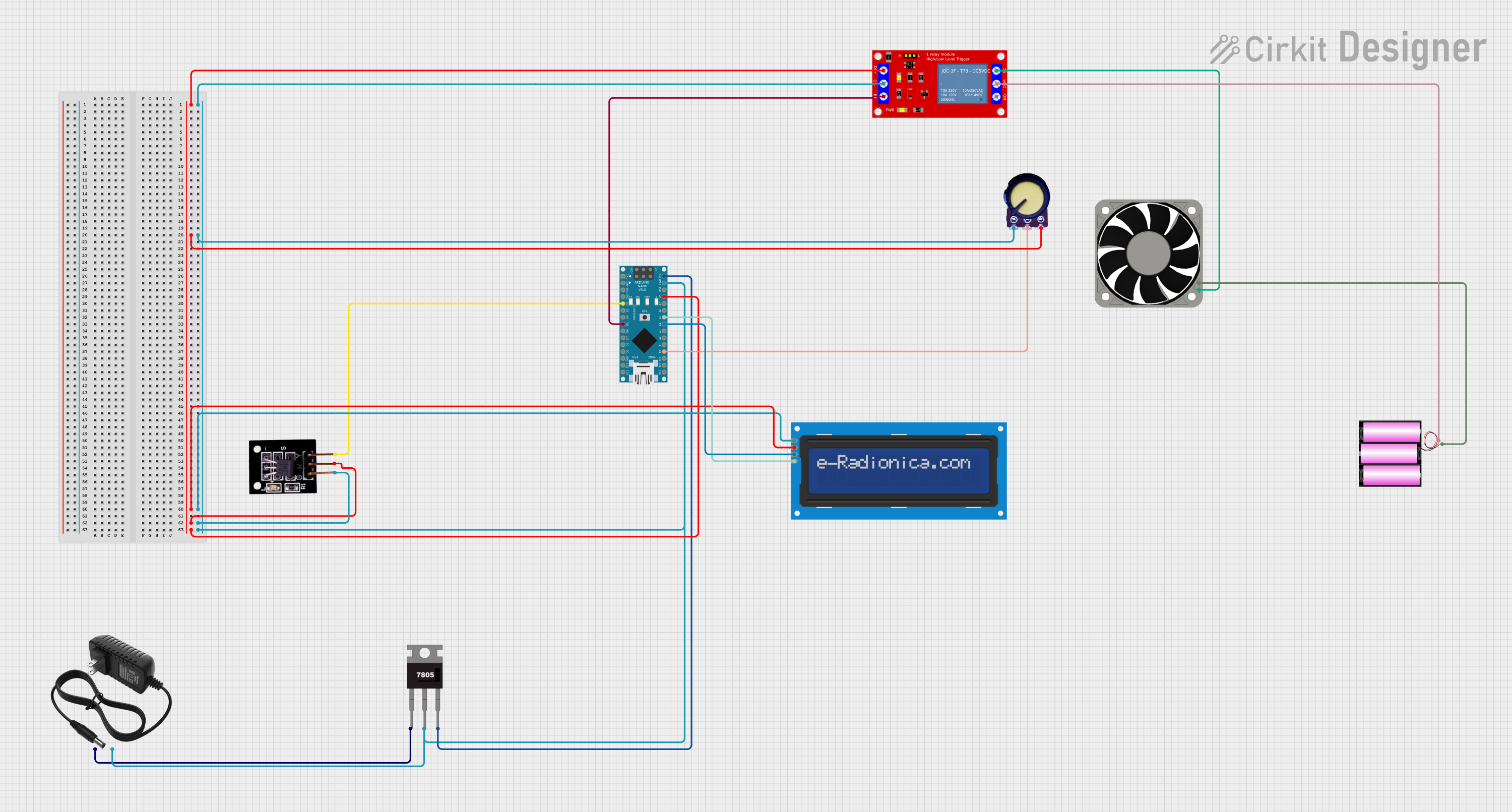
Circuit Documentation
Summary
This circuit is designed to control a fan based on temperature readings from a DS18B20 sensor. The user can set the temperature threshold using a potentiometer. The current temperature and threshold are displayed on an LCD screen. The fan is controlled via a relay module. The circuit is powered by a 12V power supply, which is regulated to 5V using a 7805 voltage regulator.
Component List
Arduino Nano
- Description: Microcontroller board based on the ATmega328P.
- Pins: D1/TX, D0/RX, RESET, GND, D2, D3, D4, D5, D6, D7, D8, D9, D10, D11/MOSI, D12/MISO, VIN, 5V, A7, A6, A5, A4, A3, A2, A1, A0, AREF, 3V3, D13/SCK
DS18B20
- Description: Digital temperature sensor.
- Pins: OUTPUT, VCC 3.3V-5V DC, GND
1 Channel 5V Relay Module
- Description: Relay module for controlling high voltage devices.
- Pins: VCC+, VCC- (GND), IN, N.O., COM, N.C.
Potentiometer
- Description: Variable resistor used to set the temperature threshold.
- Pins: GND, Output, VCC
40 Fan 12v
- Description: 12V fan for cooling.
- Pins: +12V, -12V
12v power supply
- Description: Power supply providing 12V DC.
- Pins: +, -
7805
- Description: Voltage regulator to convert 12V to 5V.
- Pins: Vin, Gnd, Vout
battery 12v
- Description: 12V battery for power.
- Pins: +, -
LCD screen 16x2 I2C
- Description: 16x2 character LCD with I2C interface.
- Pins: SCL, SDA, VCC, GND
Wiring Details
Arduino Nano
- 5V: Connected to VCC of DS18B20, VCC of Potentiometer, VCC+ of Relay Module, VCC of LCD screen.
- GND: Connected to GND of DS18B20, GND of Potentiometer, VCC- (GND) of Relay Module, GND of LCD screen, Gnd of 7805, - of 12V power supply.
- D2: Connected to OUTPUT of DS18B20.
- D5: Connected to IN of Relay Module.
- VIN: Connected to Vout of 7805.
- A5: Connected to SCL of LCD screen.
- A4: Connected to SDA of LCD screen.
- A0: Connected to Output of Potentiometer.
DS18B20
- VCC 3.3V-5V DC: Connected to 5V of Arduino Nano.
- GND: Connected to GND of Arduino Nano.
- OUTPUT: Connected to D2 of Arduino Nano.
1 Channel 5V Relay Module
- VCC+: Connected to 5V of Arduino Nano.
- VCC- (GND): Connected to GND of Arduino Nano.
- IN: Connected to D5 of Arduino Nano.
- COM: Connected to + of 12V battery.
- N.C.: Connected to +12V of 40 Fan 12v.
Potentiometer
- GND: Connected to GND of Arduino Nano.
- Output: Connected to A0 of Arduino Nano.
- VCC: Connected to 5V of Arduino Nano.
40 Fan 12v
- +12V: Connected to N.C. of Relay Module.
- -12V: Connected to - of 12V battery.
12v power supply
- +: Connected to Vin of 7805.
- -: Connected to GND of Arduino Nano.
7805
- Vin: Connected to + of 12V power supply.
- Gnd: Connected to GND of Arduino Nano.
- Vout: Connected to VIN of Arduino Nano.
battery 12v
- +: Connected to COM of Relay Module.
- -: Connected to -12V of 40 Fan 12v.
LCD screen 16x2 I2C
- SCL: Connected to A5 of Arduino Nano.
- SDA: Connected to A4 of Arduino Nano.
- VCC: Connected to 5V of Arduino Nano.
- GND: Connected to GND of Arduino Nano.
Code Documentation
// This Arduino sketch controls a fan based on temperature readings from a
// DS18B20 sensor. The user can set the temperature threshold using a
// potentiometer. The current temperature and threshold are displayed on
// an LCD screen. The fan is controlled via a relay.

#include <OneWire.h>
#include <DallasTemperature.h>
#include <Wire.h>
#include <LiquidCrystal_I2C.h>

// Pin definitions
#define ONE_WIRE_BUS 2       // DS18B20 data pin
const int potPin = A0;       // Potentiometer connected here
const int RelayPin = 5;      // Relay pin connected here

// DS18B20 setup
OneWire oneWire(ONE_WIRE_BUS);
DallasTemperature sensors(&oneWire);

// LCD setup
LiquidCrystal_I2C lcd(0x27, A4, A5); // Use working LCD address and pins

void setup() {
  sensors.begin();             // Initialize DS18B20 sensor
  pinMode(RelayPin, OUTPUT);   // Set relay pin as output
  digitalWrite(RelayPin, LOW); // Ensure relay is off initially

  Serial.begin(9600);          // Initialize serial communication for debugging

  lcd.init();                  // Initialize the LCD
  lcd.backlight();             // Turn on the backlight
  lcd.setCursor(0, 0);
  lcd.print("Temp Fan Control");
  lcd.setCursor(0, 1);
  lcd.print("by Your Name");
  delay(2000);                 // Display splash screen
  lcd.clear();
}

void loop() {
  // Read the potentiometer and map its value to a temperature range
  int threshold = map(analogRead(potPin), 0, 1023, 20, 40);

  // Request and read the temperature from the DS18B20
  sensors.requestTemperatures();
  float temperature = sensors.getTempCByIndex(0);

  // Debugging: Print values to Serial Monitor
  Serial.print("Temperature: ");
  Serial.println(temperature);
  Serial.print("Threshold: ");
  Serial.println(threshold);

  // Control the relay based on the temperature and threshold
  if (temperature > threshold) {
    digitalWrite(RelayPin, HIGH); // Turn on the fan
    Serial.println("Relay: ON");
  } else {
    digitalWrite(RelayPin, LOW);  // Turn off the fan
    Serial.println("Relay: OFF");
  }

  // Update the LCD with current temperature and threshold
  lcd.setCursor(0, 0);
  lcd.print("Temp: ");
  if (temperature == DEVICE_DISCONNECTED_C) {
    lcd.print("Error");           // Display error if sensor is disconnected
    Serial.println("Sensor Error");
  } else {
    lcd.print(temperature, 1);    // Display temperature with 1 decimal place
    lcd.print("C");
  }

  lcd.setCursor(0, 1);
  lcd.print("SetTemp: ");
  lcd.print(threshold);
  lcd.print("C");

  delay(1000); // Refresh every second
}
This code initializes the DS18B20 temperature sensor, the relay, and the LCD screen. It reads the temperature from the DS18B20 sensor and the threshold from the potentiometer. Based on the temperature and threshold, it controls the relay to turn the fan on or off. The current temperature and threshold are displayed on the LCD screen.