Cirkit Designer
Your all-in-one circuit design IDE
Home /
Project Documentation
Arduino-Controlled 12V Relay Switching for Solenoid Actuation
Circuit Documentation
Summary of the Circuit
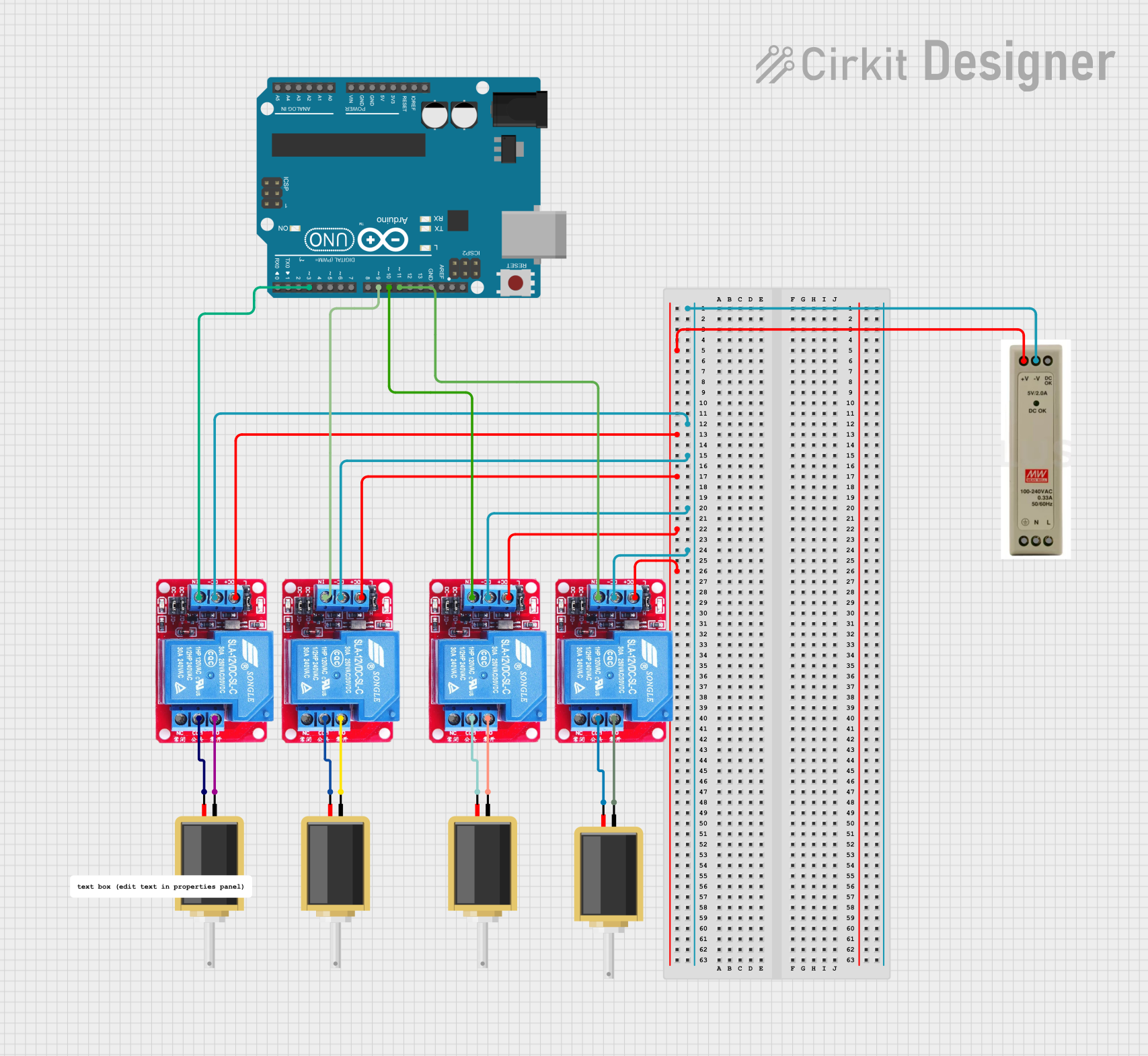
This circuit is designed to control multiple solenoids using an Arduino UNO microcontroller and a set of 12V relays. The relays are used to switch the solenoids on and off, allowing for high-current devices to be controlled by the low-current output pins of the Arduino. A 12V power supply unit (PSU) provides the necessary power to the relays and solenoids.
Component List
12V Relay
- Description: A relay is an electrically operated switch that allows a circuit to be controlled by a low-power signal, or where several circuits must be controlled by one signal.
- Pins: Normally Open (NO), Common (COM), Normally Closed (NC), DC Positive (DC+), DC Negative (DC-), Input (IN)
Arduino UNO
- Description: The Arduino UNO is a microcontroller board based on the ATmega328P. It has digital input/output pins, analog inputs, a USB connection for programming, and power management features.
- Pins: UNUSED, IOREF, Reset, 3.3V, 5V, GND, Vin, Analog (A0-A5), Serial Clock Line (SCL), Serial Data Line (SDA), Analog Reference (AREF), Digital (D0-D13)
12V PSU
- Description: A power supply unit that provides a 12V output, commonly used to power electronic devices and components.
- Pins: 12V Positive (12V+), Ground (GND), 12V OK, Protective Earth (PE), Neutral (N), Line (L)
Solenoid
- Description: An electromechanical device that converts electrical energy into mechanical motion when energized.
- Pins: pin1, pin2
Comment
- Description: A placeholder or annotation within the circuit design, typically used to provide additional information or instructions.
Wiring Details
12V Relay
- DC+: Connected to the 12V+ output of the 12V PSU.
- DC-: Connected to the GND of the 12V PSU.
- IN: Controlled by a digital output pin (D3, D9, D10, or D11) of the Arduino UNO.
- NO: Connected to pin1 of a corresponding Solenoid.
- COM: Connected to pin2 of the same Solenoid.
Arduino UNO
- D3, D9, D10, D11: Each connected to the IN pin of a different 12V Relay.
- GND: Common ground reference for the circuit.
12V PSU
- 12V+: Provides power to the DC+ pins of all 12V Relays.
- GND: Provides a common ground for the DC- pins of all 12V Relays and the Arduino UNO.
Solenoid
- pin1: Connected to the NO pin of a corresponding 12V Relay.
- pin2: Connected to the COM pin of the same 12V Relay.
Documented Code
Arduino UNO Code (sketch.ino)
void setup() {
  // put your setup code here, to run once:

}

void loop() {
  // put your main code here, to run repeatedly:

}
Additional Notes (documentation.txt)
No additional code documentation provided.