Cirkit Designer
Your all-in-one circuit design IDE
Home /
Project Documentation
Arduino UNO-Based Motion-Activated LED and Fan System with I2C LCD Display
Circuit Documentation
Summary
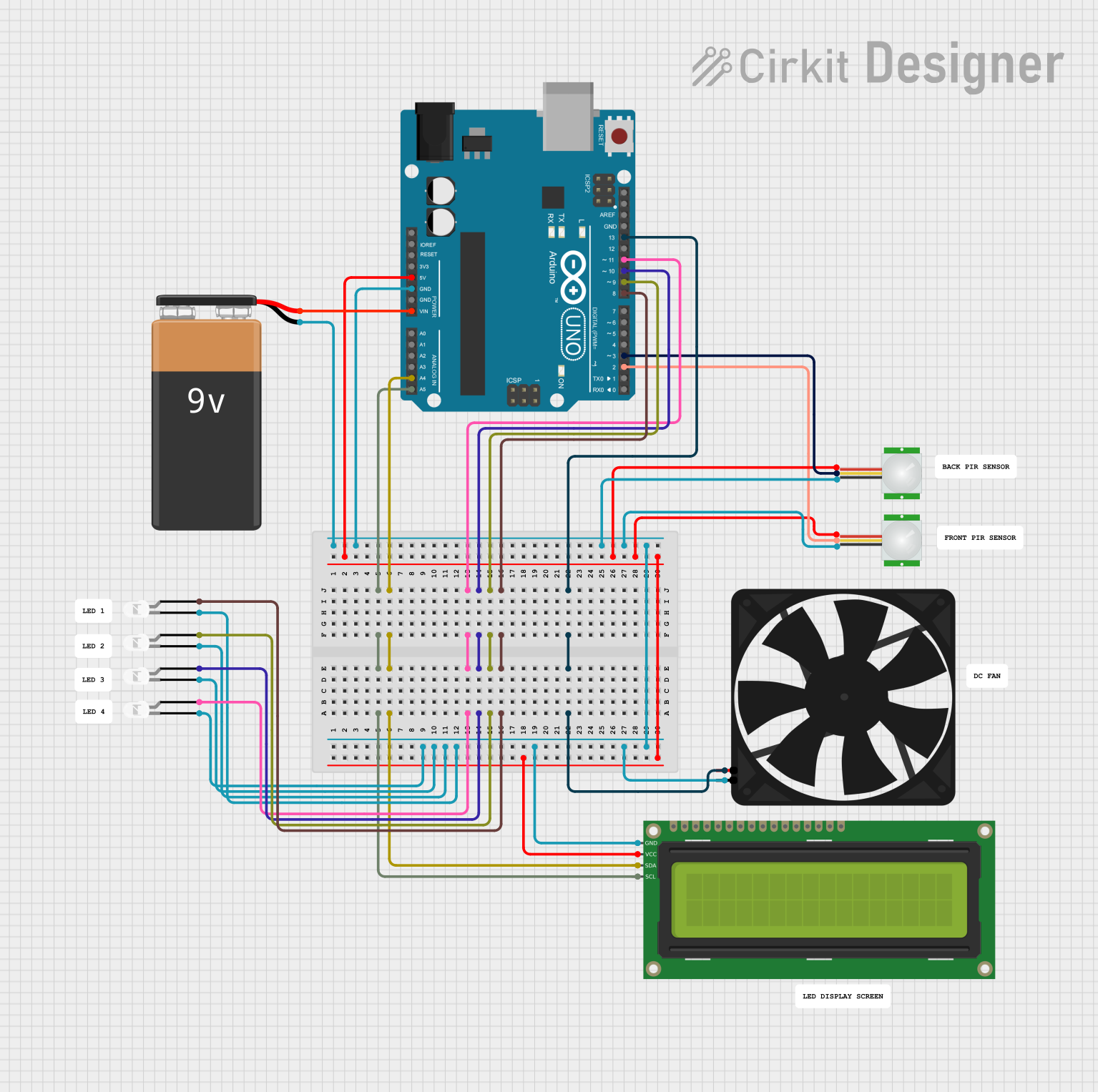
This circuit involves an Arduino UNO microcontroller interfacing with various components including a 16x2 I2C LCD, multiple PIR sensors, several white LEDs, and a fan. The circuit is powered by a 9V battery. The Arduino UNO is used to control the LEDs and the fan based on the input from the PIR sensors, and to display information on the LCD.
Component List
Arduino UNO
- Description: A microcontroller board based on the ATmega328P.
- Pins: UNUSED, IOREF, Reset, 3.3V, 5V, GND, Vin, A0, A1, A2, A3, A4, A5, SCL, SDA, AREF, D13, D12, D11, D10, D9, D8, D7, D6, D5, D4, D3, D2, D1, D0
PIR sensor
- Description: A passive infrared sensor used to detect motion.
- Pins: VDD, SIG, GND
16x2 I2C LCD
- Description: A 16x2 character LCD with I2C interface.
- Pins: GND, VCC, SDA, SCL
LED: Two Pin (white)
- Description: A white LED with two pins.
- Pins: cathode, anode
Fan
- Description: A small fan powered by 5V.
- Pins: GND, 5V
9V Battery
- Description: A 9V battery used to power the circuit.
- Pins: -, +
Wiring Details
Arduino UNO
- A5: Connected to SCL of 16x2 I2C LCD
- A4: Connected to SDA of 16x2 I2C LCD
- D11: Connected to anode of one white LED
- D10: Connected to anode of another white LED
- D9: Connected to anode of another white LED
- D8: Connected to anode of another white LED
- D13: Connected to 5V of Fan
- GND: Connected to - of 9V Battery, GND of both PIR sensors, cathode of all white LEDs, GND of 16x2 I2C LCD, and GND of Fan
- 5V: Connected to VDD of both PIR sensors and VCC of 16x2 I2C LCD
- Vin: Connected to + of 9V Battery
- D3: Connected to SIG of one PIR sensor
- D2: Connected to SIG of another PIR sensor
16x2 I2C LCD
- SCL: Connected to A5 of Arduino UNO
- SDA: Connected to A4 of Arduino UNO
- GND: Connected to GND of Arduino UNO
- VCC: Connected to 5V of Arduino UNO
PIR sensor
- VDD: Connected to 5V of Arduino UNO
- SIG: Connected to D3 of Arduino UNO (for one sensor) and D2 of Arduino UNO (for another sensor)
- GND: Connected to GND of Arduino UNO
LED: Two Pin (white)
- anode: Connected to D11, D10, D9, and D8 of Arduino UNO (one LED per pin)
- cathode: Connected to GND of Arduino UNO
Fan
- 5V: Connected to D13 of Arduino UNO
- GND: Connected to GND of Arduino UNO
9V Battery
- -: Connected to GND of Arduino UNO
- +: Connected to Vin of Arduino UNO
Documented Code
sketch.ino
void setup() {
  // put your setup code here, to run once:

}

void loop() {
  // put your main code here, to run repeatedly:

}
documentation.txt