
Arduino Nano-Based Smart Irrigation System with Soil Moisture and Light Sensors
View and Edit Project In Cirkit Designer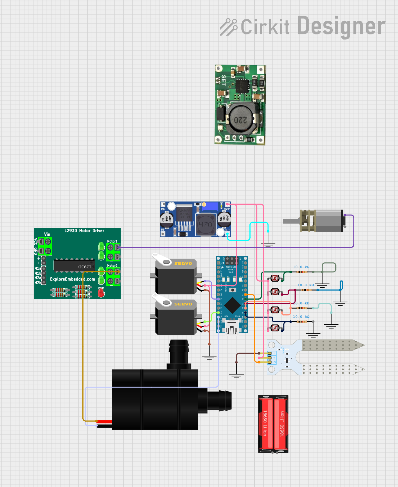
Circuit Documentation
Summary
This circuit involves an Arduino Nano microcontroller interfacing with various sensors and actuators, including photocells (LDRs), resistors, servos, a water pump, a soil moisture sensor, a buck converter, and a motor driver. The circuit is designed to read sensor data and control actuators accordingly.
Component List
Arduino Nano
- Description: A small, complete, and breadboard-friendly board based on the ATmega328P.
- Pins: D1/TX, D0/RX, RESET, GND, D2, D3, D4, D5, D6, D7, D8, D9, D10, D11/MOSI, D12/MISO, VIN, 5V, A7, A6, A5, A4, A3, A2, A1, A0, AREF, 3V3, D13/SCK
Photocell (LDR)
- Description: A light-dependent resistor used to detect light levels.
- Pins: pin 0, pin 1
Resistor
- Description: A 10k Ohm resistor used to limit current.
- Pins: pin1, pin2
- Properties: Resistance: 10k Ohms
GND
- Description: Ground connection.
- Pins: GND
Servo
- Description: A servo motor used for precise control of angular position.
- Pins: gnd, vcc, pulse
Buck Converter
- Description: A DC-DC converter used to step down voltage.
- Pins: IN+, IN-, OUT+, OUT-
Water Pump
- Description: A small water pump used for liquid transfer.
- Pins: +, -
TP5100
- Description: A battery charging module.
- Pins: B-, B+, IN-, IN+
Soil Moisture Sensor
- Description: A sensor used to measure the moisture level in the soil.
- Pins: VCC, GND, SIG
18650 Li-Ion
- Description: A rechargeable lithium-ion battery.
- Pins: Positive, Negative
DC Mini Metal Gear Motor
- Description: A small DC motor with metal gears.
- Pins: IN1, IN2
L293D Motor Driver
- Description: A motor driver IC used to control motors.
- Pins: pin 1, pin 2, pin 10, pin 9, pin 12, pin 11, pin 5, pin 6, pin 7, pin 8, pin 3, pin 4
Wiring Details
Arduino Nano
- D6: Connected to Servo (pulse)
- D9: Connected to Servo (pulse)
- D10: Connected to Water Pump (-)
- A4: Connected to Soil Moisture Sensor (SIG)
- A3: Connected to Resistor (pin1) and Photocell (LDR) (pin 1)
- A2: Connected to Resistor (pin1) and Photocell (LDR) (pin 1)
- A1: Connected to Resistor (pin1) and Photocell (LDR) (pin 1)
- A0: Connected to Resistor (pin1) and Photocell (LDR) (pin 1)
Photocell (LDR)
- pin 0: Connected to Buck Converter (OUT+), Servo (vcc), Soil Moisture Sensor (VCC)
- pin 1: Connected to Resistor (pin1) and Arduino Nano (A3, A2, A1, A0)
Resistor
- pin1: Connected to Photocell (LDR) (pin 1) and Arduino Nano (A3, A2, A1, A0)
- pin2: Connected to GND
Servo
- pulse: Connected to Arduino Nano (D6, D9)
- vcc: Connected to Buck Converter (OUT+), Photocell (LDR) (pin 0)
- gnd: Connected to GND
Buck Converter
- OUT+: Connected to Photocell (LDR) (pin 0), Servo (vcc), Soil Moisture Sensor (VCC)
- OUT-: Connected to GND
Water Pump
- -: Connected to Arduino Nano (D10)
- +: Connected to L293D Motor Driver (pin 11)
Soil Moisture Sensor
- SIG: Connected to Arduino Nano (A4)
- VCC: Connected to Buck Converter (OUT+), Photocell (LDR) (pin 0)
- GND: Connected to GND
DC Mini Metal Gear Motor
- IN2: Connected to L293D Motor Driver (pin 9)
L293D Motor Driver
- pin 11: Connected to Water Pump (+)
- pin 9: Connected to DC Mini Metal Gear Motor (IN2)
GND
- GND: Connected to Resistor (pin2), Servo (gnd), Buck Converter (OUT-), Soil Moisture Sensor (GND)
Documented Code
Arduino Nano Code (sketch.ino)
void setup() {
  // put your setup code here, to run once:

}

void loop() {
  // put your main code here, to run repeatedly:

}
Documentation (documentation.txt)
This documentation provides a comprehensive overview of the circuit, including a summary, component list, wiring details, and the code used in the microcontroller.