
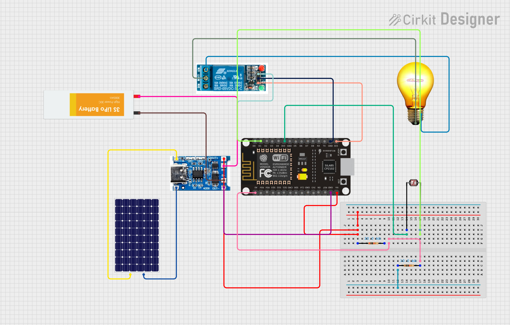
Energy Tracking System Documentation
Summary
This Energy Tracking System uses a solar panel to charge a battery during the day and powers an AC bulb at night. The system status, including charging state and battery life, is sent to an IoT application. The bulb is controlled based on the light level detected by a Light Dependent Resistor (LDR). The system is built around an ESP8266 NodeMCU microcontroller.
Component List
ESP8266 NodeMCU
- Description: A low-cost Wi-Fi microcontroller with GPIO, ADC, and PWM capabilities.
- Pins: D0, D1, D2, D3, D4, 3V3, GND, D5, D6, D7, D8, RX, TX, A0, RSV, SD3, SD2, SD1, CMD, SD0, CLK, EN, RST, VIN
TP4056 Battery Charging Protection Module (Type C)
- Description: A module for charging and protecting LiPo batteries.
- Pins: OUT +, B+, B-, OUT -, +, -
Solar Panel
- Description: A device that converts sunlight into electrical energy.
- Pins: +, -
5V Relay
- Description: An electromechanical switch used to control high voltage devices.
- Pins: Normally Open, Common terminal, Normally Closed, In, GND, VCC
AC Bulb
- Description: A standard AC-powered light bulb.
- Pins: P, N
Photocell (LDR)
- Description: A light-dependent resistor that changes resistance based on light levels.
- Pins: pin 0, pin 1
Resistor (10k Ohms)
- Description: A resistor with a resistance of 10,000 Ohms.
- Pins: pin1, pin2
Resistor (20k Ohms)
- Description: A resistor with a resistance of 20,000 Ohms.
- Pins: pin1, pin2
LiPo Battery
- Description: A rechargeable lithium polymer battery.
- Pins: VCC, GND
Wiring Details
ESP8266 NodeMCU
- VIN: Connected to pin1 of the 20k Ohm Resistor and OUT + of the TP4056 Battery Charging Protection Module.
- A0: Connected to pin2 of the 10k Ohm Resistor.
- 3V3: Connected to pin 0 of the Photocell (LDR) and VCC of the 5V Relay.
- GND: Connected to GND of the 5V Relay and OUT - of the TP4056 Battery Charging Protection Module.
- D0: Connected to In of the 5V Relay.
- D1: Connected to pin 1 of the Photocell (LDR).
TP4056 Battery Charging Protection Module (Type C)
- OUT +: Connected to VIN of the ESP8266 NodeMCU and pin1 of the 20k Ohm Resistor.
- OUT -: Connected to GND of the ESP8266 NodeMCU.
- B+: Connected to VCC of the LiPo Battery.
- B-: Connected to GND of the LiPo Battery.
- +: Connected to + of the Solar Panel.
- -: Connected to - of the Solar Panel.
Solar Panel
- +: Connected to + of the TP4056 Battery Charging Protection Module.
- -: Connected to - of the TP4056 Battery Charging Protection Module.
5V Relay
- In: Connected to D0 of the ESP8266 NodeMCU.
- GND: Connected to GND of the ESP8266 NodeMCU.
- VCC: Connected to 3V3 of the ESP8266 NodeMCU.
- Normally Open: Connected to N of the AC Bulb.
- Common terminal: Connected to P of the AC Bulb.
AC Bulb
- N: Connected to Normally Open of the 5V Relay.
- P: Connected to Common terminal of the 5V Relay.
Photocell (LDR)
- pin 0: Connected to 3V3 of the ESP8266 NodeMCU.
- pin 1: Connected to D1 of the ESP8266 NodeMCU.
Resistor (10k Ohms)
- pin1: Not connected.
- pin2: Connected to A0 of the ESP8266 NodeMCU.
Resistor (20k Ohms)
- pin1: Connected to VIN of the ESP8266 NodeMCU and OUT + of the TP4056 Battery Charging Protection Module.
- pin2: Not connected.
LiPo Battery
- VCC: Connected to B+ of the TP4056 Battery Charging Protection Module.
- GND: Connected to B- of the TP4056 Battery Charging Protection Module.
Code Documentation
/*
 * Energy Tracking System
 * This system uses a solar panel to charge a battery during the day and powers
 * an AC bulb at night. The system status, including charging state and battery
 * life, is sent to an IoT application. The bulb is controlled based on the
 * light level detected by an LDR.
 */

#include <ESP8266WiFi.h>
#include <ESP8266HTTPClient.h>

const char* ssid = "your_SSID";
const char* password = "your_PASSWORD";
const char* serverName = "http://your_server.com/update";

#define LDR_PIN D1
#define RELAY_PIN D0
#define BATTERY_PIN A0

void setup() {
  Serial.begin(115200);
  pinMode(LDR_PIN, INPUT);
  pinMode(RELAY_PIN, OUTPUT);
  WiFi.begin(ssid, password);
  while (WiFi.status() != WL_CONNECTED) {
    delay(1000);
    Serial.println("Connecting to WiFi...");
  }
  Serial.println("Connected to WiFi");
}

void loop() {
  int ldrValue = analogRead(LDR_PIN);
  int batteryValue = analogRead(BATTERY_PIN);
  bool isCharging = digitalRead(VIN) > 0;
  bool isNight = ldrValue < 500;
  digitalWrite(RELAY_PIN, isNight ? HIGH : LOW);
  sendDataToServer(isCharging, batteryValue, isNight);
  delay(60000); // Update every minute
}

void sendDataToServer(bool isCharging, int batteryValue, bool isNight) {
  if (WiFi.status() == WL_CONNECTED) {
    HTTPClient http;
    String serverPath = serverName + "?charging=" + (isCharging ? "1" : "0") +
                       "&battery=" + String(batteryValue) +
                       "&light=" + (isNight ? "1" : "0");
    http.begin(serverPath.c_str());
    int httpResponseCode = http.GET();
    if (httpResponseCode > 0) {
      String response = http.getString();
      Serial.println(httpResponseCode);
      Serial.println(response);
    } else {
      Serial.print("Error on sending GET: ");
      Serial.println(httpResponseCode);
    }
    http.end();
  } else {
    Serial.println("WiFi Disconnected");
  }
}
This code initializes the ESP8266 NodeMCU, connects it to a Wi-Fi network, and reads values from the LDR and battery. It controls the relay based on the light level and sends the system status to a server every minute.