
Arduino UNO Motion-Activated LED Strip with HC-SR501 and TIP120
View and Edit Project In Cirkit Designer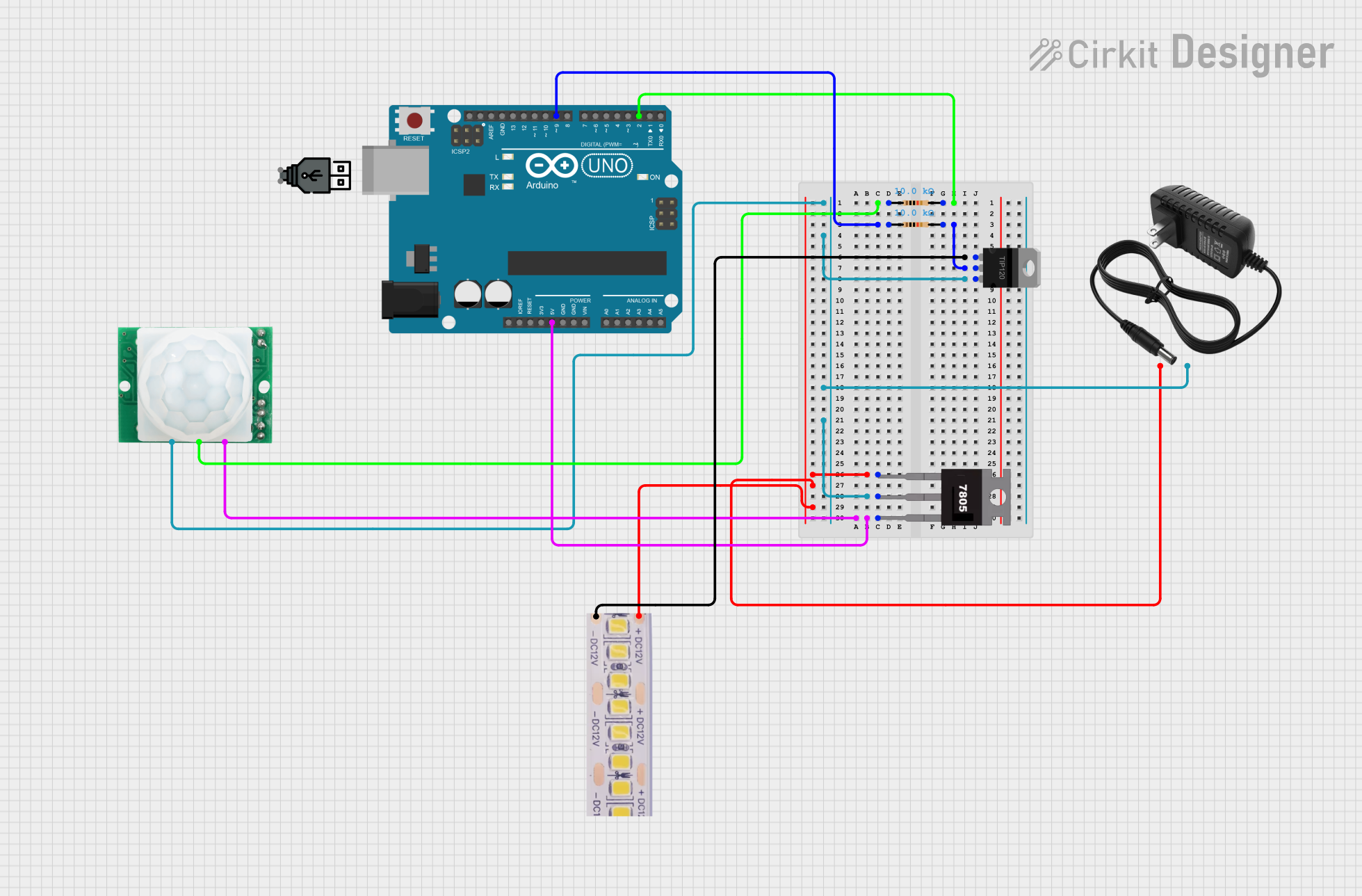
Circuit Documentation
Summary
This circuit is designed to control a 12V white LED strip using an Arduino UNO and a motion sensor (HC-SR501). The circuit includes a TIP120 transistor to handle the high current required by the LED strip, and a 7805 voltage regulator to provide a stable 5V supply to the Arduino and the motion sensor. The motion sensor detects movement and sends a signal to the Arduino, which then controls the LED strip through the transistor.
Component List
Arduino UNO
- Description: Microcontroller board based on the ATmega328P.
- Pins: UNUSED, IOREF, Reset, 3.3V, 5V, GND, Vin, A0, A1, A2, A3, A4, A5, SCL, SDA, AREF, D13, D12, D11, D10, D9, D8, D7, D6, D5, D4, D3, D2, D1, D0
HC-SR501 Motion Sensor
- Description: Passive infrared (PIR) motion sensor.
- Pins: GND, OUT, VCC
TIP120 Hi-Current Darlington Transistor
- Description: NPN power transistor.
- Pins: BASE, COLLECTOR, EMITTER
Resistor (10k Ohms)
- Description: Resistor with a resistance of 10k Ohms.
- Pins: pin1, pin2
7805 Voltage Regulator
- Description: 5V voltage regulator.
- Pins: Vin, Gnd, Vout
12V Power Supply
- Description: 12V DC power supply.
- Pins: +, -
12V White LED Strip
- Description: LED strip that operates at 12V.
- Pins: +12V, GND
USB Power
- Description: USB power supply.
- Pins: +, -
Wiring Details
Arduino UNO
- D2 is connected to pin2 of the first 10k Ohm resistor.
- D9 is connected to pin1 of the second 10k Ohm resistor.
- 5V is connected to Vout of the 7805 voltage regulator.
HC-SR501 Motion Sensor
- OUT is connected to pin1 of the first 10k Ohm resistor.
- GND is connected to EMITTER of the TIP120 transistor, Gnd of the 7805 voltage regulator, and - of the 12V power supply.
- VCC is connected to Vout of the 7805 voltage regulator.
TIP120 Hi-Current Darlington Transistor
- BASE is connected to GND of the 12V white LED strip.
- COLLECTOR is connected to pin2 of the second 10k Ohm resistor.
- EMITTER is connected to Gnd of the 7805 voltage regulator, GND of the HC-SR501 motion sensor, and - of the 12V power supply.
Resistor (10k Ohms)
- First Resistor:
- pin1 is connected to OUT of the HC-SR501 motion sensor.
- pin2 is connected to D2 of the Arduino UNO.
- Second Resistor:
- pin1 is connected to D9 of the Arduino UNO.
- pin2 is connected to COLLECTOR of the TIP120 transistor.
7805 Voltage Regulator
- Vin is connected to + of the 12V power supply and +12V of the 12V white LED strip.
- Gnd is connected to EMITTER of the TIP120 transistor, GND of the HC-SR501 motion sensor, and - of the 12V power supply.
- Vout is connected to VCC of the HC-SR501 motion sensor and 5V of the Arduino UNO.
12V Power Supply
- + is connected to Vin of the 7805 voltage regulator and +12V of the 12V white LED strip.
- - is connected to Gnd of the 7805 voltage regulator, EMITTER of the TIP120 transistor, and GND of the HC-SR501 motion sensor.
12V White LED Strip
- +12V is connected to + of the 12V power supply and Vin of the 7805 voltage regulator.
- GND is connected to BASE of the TIP120 transistor.
Documented Code
Arduino UNO Code (sketch.ino)
void setup() {
  // put your setup code here, to run once:

}

void loop() {
  // put your main code here, to run repeatedly:

}
Additional Documentation (documentation.txt)
This documentation provides a comprehensive overview of the circuit, including a summary, detailed component list, wiring details, and the code used in the Arduino UNO.