Arduino Uno R3 Bluetooth-Controlled Robot with OLED Display
Circuit Documentation
Summary of the Circuit
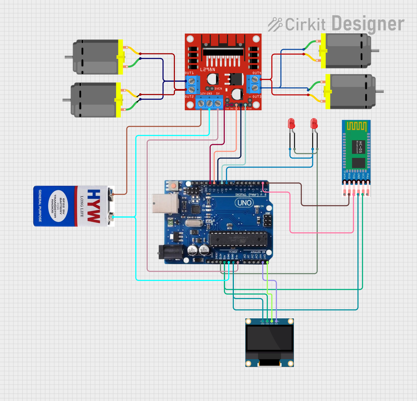
This circuit is designed to control a set of DC motors using an Arduino Uno R3 microcontroller, interfaced with an L298N DC motor driver. The system can be controlled wirelessly via an HC-05 Bluetooth module. The circuit also includes two red LEDs for indication purposes and a 0.96" OLED display for visual output. The entire circuit is powered by a 9V battery.
Component List
Microcontroller
- Arduino Uno R3: A microcontroller board based on the ATmega328P. It has digital input/output pins, analog inputs, a USB connection for programming, and power management features.
Motor Driver
- L298N DC Motor Driver: A module capable of driving two DC motors or one stepper motor. It provides the necessary current and voltage for the motors and includes built-in diodes for back EMF protection.
Motors
- DC Motors: Four identical motors used for movement. Each motor has two pins: one for the positive supply and one for the ground connection.
Bluetooth Module
- HC-05: A Bluetooth module that allows for wireless communication with the Arduino. It has pins for power, ground, transmit (TX), receive (RX), and state indication.
Display
- 0.96" OLED: A small display that uses the I2C protocol for communication. It has pins for power (VDD), ground (GND), serial clock (SCK), and serial data (SDA).
LEDs
- LED: Two Pin (red): Two red LEDs used for indication. Each LED has an anode and a cathode pin.
Power Source
- 9V Battery: Provides power to the circuit. It has a positive and a negative terminal.
Wiring Details
Arduino Uno R3
- 3.3V connected to the anodes of two red LEDs.
- 5V connected to the VCC of HC-05 and VDD of the OLED display.
- GND connected to the ground of the 9V battery, L298N motor driver, HC-05, and OLED display.
- VIN connected to the 5V input of the L298N motor driver.
- A4/SDA connected to the SDA of the OLED display.
- A5/SCL connected to the SCK of the OLED display.
- Digital Pins 13, 12, 11, 10 connected to the IN1, IN2, IN3, IN4 of the L298N motor driver respectively.
- Digital Pin 9 connected to the cathodes of two red LEDs.
- Digital Pin 1 (TX) connected to the RXD of HC-05.
- Digital Pin 0 (RX) connected to the TXD of HC-05.
L298N DC Motor Driver
- OUT1 and OUT2 connected to pins 1 and 2 of two DC motors.
- OUT3 and OUT4 connected to pins 1 and 2 of the other two DC motors.
- 12V connected to the positive terminal of the 9V battery.
- GND connected to the ground of the 9V battery.
DC Motors
- Pin 1 and Pin 2 of each motor connected to the corresponding OUT pins on the L298N motor driver.
HC-05 Bluetooth Module
- VCC connected to the 5V output of the Arduino Uno R3.
- GND connected to the ground of the Arduino Uno R3.
- TXD connected to the RX (Pin 0) of the Arduino Uno R3.
- RXD connected to the TX (Pin 1) of the Arduino Uno R3.
0.96" OLED Display
- VDD connected to the 5V output of the Arduino Uno R3.
- GND connected to the ground of the Arduino Uno R3.
- SDA connected to the A4/SDA of the Arduino Uno R3.
- SCK connected to the A5/SCL of the Arduino Uno R3.
LEDs
- Anode of each LED connected to the 3.3V output of the Arduino Uno R3.
- Cathode of each LED connected to the Digital Pin 9 of the Arduino Uno R3.
9V Battery
- Positive (+) terminal connected to the 12V input of the L298N motor driver.
- Negative (-) terminal connected to the ground of the circuit.
Documented Code
Arduino Uno R3 Code
#include <Wire.h>
#include <Adafruit_GFX.h>
#include <Adafruit_SSD1306.h>

// Configuration for OLED
#define SCREEN_WIDTH 128
#define SCREEN_HEIGHT 64
Adafruit_SSD1306 display(SCREEN_WIDTH, SCREEN_HEIGHT, &Wire, -1);

// Variables for running text
String text1 = "SMKN 26 Jakarta";
String text2 = "XII TTL 3";
int textPosition = SCREEN_WIDTH;  // Start from the right of the screen
unsigned long previousMillis = 0;
const long interval = 30;         // Speed of running text (smaller is faster)
bool showText1 = true;

char t;

void setup() {
  // Initialize motor and LED pins
  pinMode(13, OUTPUT); // Left motor forward
  pinMode(12, OUTPUT); // Left motor reverse
  pinMode(11, OUTPUT); // Right motor forward
  pinMode(10, OUTPUT); // Right motor reverse
  pinMode(9, OUTPUT);  // LED
  Serial.begin(9600);  // Start serial communication for Bluetooth

  // Initialize OLED
  if (!display.begin(SSD1306_SWITCHCAPVCC, 0x3C)) {
    Serial.println(F("SSD1306 allocation failed"));
    for (;;);
  }
  display.clearDisplay();
}

void loop() {
  // Control motors and LED based on input from Bluetooth
  if (Serial.available()) {
    t = Serial.read();
    Serial.println(t);  // Display received character in Serial Monitor (for debugging)
  }

  // Motor and LED control logic based on received character
  if (t == 'F') { // Forward
    digitalWrite(13, HIGH);
    digitalWrite(11, HIGH);
    digitalWrite(12, LOW);
    digitalWrite(10, LOW);
  } else if (t == 'B') { // Reverse
    digitalWrite(12, HIGH);
    digitalWrite(10, HIGH);
    digitalWrite(13, LOW);
    digitalWrite(11, LOW);
  } else if (t == 'L') { // Turn right
    digitalWrite(11, HIGH);
    digitalWrite(13, LOW);
    digitalWrite(12, LOW);
    digitalWrite(10, LOW);
  } else if (t == 'R') { // Turn left
    digitalWrite(13, HIGH);
    digitalWrite(11, LOW);
    digitalWrite(12, LOW);
    digitalWrite(10, LOW);
  } else if (t == 'W') { // LED ON
    digitalWrite(9, HIGH);
  } else if (t == 'w') { // LED OFF
    digitalWrite(9, LOW);
  } else if (t == 'S') { // STOP
    digitalWrite(13, LOW);
    digitalWrite(12, LOW);
    digitalWrite(11, LOW);
    digitalWrite(10, LOW);
  }

  // Running text display logic
  unsigned long currentMillis = millis();
  if (currentMillis - previousMillis >= interval) {
    previousMillis = currentMillis;

    display.clearDisplay();
    display.setTextSize(1);
    display.setTextColor(SSD1306_WHITE);

    if (showText1) {
      display.setCursor(textPosition, 0);
      display.print(text1);
      display.display();

      // Move text position to the left
      textPosition--;

      // Reset text position after it leaves the screen
      if (textPosition < -display.width()) {
        textPosition = SCREEN_WIDTH;  // Back to the right of the screen
        showText1 = false;            // Show text2 after text1
      }
    } else {
      // Display text2 (static)
      display.setCursor((SCREEN_WIDTH - (text2.length() * 6)) / 2, 0);  // Center text2
      display.print(text2);
      display.display();

      // Show text1 again after some time
      if (currentMillis - previousMillis >= 3000) {  // Change text after 3 seconds
        previousMillis = currentMillis;
        textPosition = SCREEN_WIDTH;  // Reset position for text1
        showText1 = true;             // Back to running text text1
      }
    }
  }
}
This code is responsible for controlling the motors and LEDs based on Bluetooth input, as well as managing the display of running text on the OLED screen. The code includes setup for the OLED display and motor control pins, and the main loop handles Bluetooth communication and motor/LED control logic. The running text feature alternates between two strings, with one scrolling across the display and the other displayed statically in the center.