
RFID-Controlled Solenoid Door Lock with Arduino and Buzzer Alert
View and Edit Project In Cirkit Designer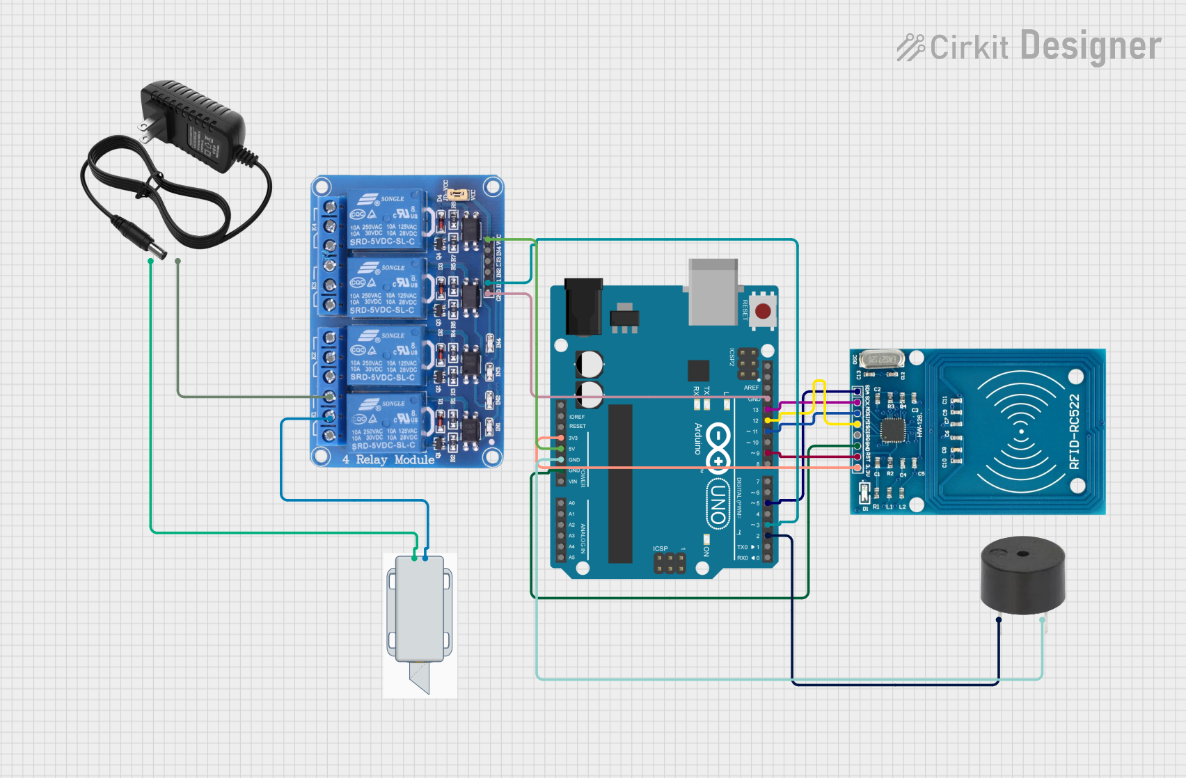
Circuit Documentation
Summary of the Circuit
This circuit is designed to control a 12V solenoid lock using an Arduino UNO microcontroller in conjunction with an RFID-RC522 reader. When an authorized RFID card is presented to the reader, the Arduino activates a relay, which in turn powers the solenoid lock, unlocking it for a predetermined amount of time. Additionally, the circuit includes a buzzer that is activated when an unauthorized card is detected.
Component List
12V Solenoid Lock
- Description: An electromechanical lock that is actuated by a 12V DC supply.
- Purpose: To lock or unlock a physical mechanism when energized or de-energized.
RFID-RC522
- Description: An RFID module that operates at 13.56 MHz for reading and writing to RFID tags.
- Purpose: To read RFID tags and communicate the tag's information to the microcontroller for access control.
Arduino UNO
- Description: A microcontroller board based on the ATmega328P, with digital and analog I/O pins.
- Purpose: To serve as the central processing unit of the circuit, controlling the RFID reader, relay, and buzzer based on programmed logic.
Buzzer
- Description: An electronic buzzer capable of emitting an audible alert.
- Purpose: To provide an audible indication of an unauthorized access attempt.
12V Power Supply
- Description: A power source that provides a 12V DC output.
- Purpose: To supply power to the solenoid lock and the relay module.
Relay 4 Channel 5V
- Description: A 4-channel relay module with 5V operating voltage.
- Purpose: To electrically isolate and control the high-power circuit of the solenoid lock from the low-power control signals from the Arduino.
Wiring Details
12V Solenoid Lock
- "+" (Positive): Connected to the 12V output of the power supply.
- "-" (Negative): Connected to the common (COM1) terminal of the relay module.
RFID-RC522
- VCC (3.3V): Connected to the 3.3V output of the Arduino UNO.
- RST: Connected to digital pin D9 of the Arduino UNO.
- GND: Connected to a ground (GND) pin of the Arduino UNO.
- IRQ: Not connected in this circuit.
- MISO: Connected to digital pin D12 of the Arduino UNO.
- MOSI: Connected to digital pin D11 of the Arduino UNO.
- SCK: Connected to digital pin D13 of the Arduino UNO.
- SDA: Connected to digital pin D5 of the Arduino UNO.
Arduino UNO
- 3.3V: Provides power to the RFID-RC522.
- 5V: Provides power to the relay module.
- GND: Common ground for the RFID-RC522, buzzer, and relay module.
- Digital Pins (D2, D3, D5, D9, D11, D12, D13): Control pins for the buzzer, relay, and RFID-RC522.
Buzzer
- PIN: Connected to digital pin D2 of the Arduino UNO.
- GND: Connected to a ground (GND) pin of the Arduino UNO.
12V Power Supply
- "+" (Positive): Provides power to the solenoid lock.
- "-" (Negative): Connected to the normally open (NO1) terminal of the relay module.
Relay 4 Channel 5V
- GND: Connected to a ground (GND) pin of the Arduino UNO.
- IN1: Connected to digital pin D3 of the Arduino UNO.
- VCC: Connected to the 5V output of the Arduino UNO.
- COM1: Connected to the negative terminal of the solenoid lock.
- NO1: Connected to the negative terminal of the 12V power supply.
Documented Code
#include <SPI.h>
#include <MFRC522.h>

#define SS_PIN 10     // Slave Select pin for RFID
#define RST_PIN 9     // Reset pin for RFID
#define RELAY_PIN 7   // Relay control pin for the lock
#define BUZZER_PIN 6  // Buzzer pin

MFRC522 rfid(SS_PIN, RST_PIN); // Create an instance of the RFID module

// Predefined authorized card ID (replace this with your actual RFID card UID)
byte authorizedUID[] = {0xDE, 0xAD, 0xBE, 0xEF}; // Update with actual UID of your card

void setup() {
  Serial.begin(9600);        // Initialize serial communication
  SPI.begin();               // Start SPI bus
  rfid.PCD_Init();           // Initialize RFID reader

  pinMode(RELAY_PIN, OUTPUT);  // Set relay pin as output
  pinMode(BUZZER_PIN, OUTPUT); // Set buzzer pin as output

  digitalWrite(RELAY_PIN, LOW);  // Start with the lock closed (relay off)
  digitalWrite(BUZZER_PIN, LOW); // Buzzer off initially

  Serial.println("Place your card on the reader...");
}

void loop() {
  // Look for new RFID cards
  if (!rfid.PICC_IsNewCardPresent()) {
    return;
  }

  // Select the RFID card
  if (!rfid.PICC_ReadCardSerial()) {
    return;
  }

  // Show the UID of the card
  Serial.print("UID: ");
  for (byte i = 0; i < rfid.uid.size; i++) {
    Serial.print(rfid.uid.uidByte[i], HEX);
    Serial.print(" ");
  }
  Serial.println();

  // Compare the read UID with the authorized UID
  if (checkUID()) {
    // Authorized card
    Serial.println("Authorized card. Unlocking the door...");
    digitalWrite(RELAY_PIN, HIGH);  // Unlock (relay on)
    delay(5000);                    // Keep the door unlocked for 5 seconds
    digitalWrite(RELAY_PIN, LOW);   // Lock the door (relay off)
  } else {
    // Unauthorized card
    Serial.println("Unauthorized card. Buzzing...");
    digitalWrite(BUZZER_PIN, HIGH); // Buzz (buzzer on)
    delay(3000);                    // Buzz for 3 seconds
    digitalWrite(BUZZER_PIN, LOW);  // Turn off the buzzer
  }

  rfid.PICC_HaltA(); // Halt RFID reader
}

// Function to check if the scanned UID matches the authorized UID
bool checkUID() {
  if (rfid.uid.size != sizeof(authorizedUID)) {
    return false;  // UID sizes don't match
  }

  for (byte i = 0; i < rfid.uid.size; i++) {
    if (rfid.uid.uidByte[i] != authorizedUID[i]) {
      return false;  // UID bytes don't match
    }
  }

  return true;  // All bytes match, card is authorized
}
Note: The code provided is for the Arduino UNO microcontroller. It initializes the RFID reader and sets up the relay and buzzer pins. When an RFID card is presented, it checks if the UID matches the authorized UID and either unlocks the door (activates the relay) or sounds the buzzer if unauthorized. The relay and buzzer are controlled using digital pins D3 and D2, respectively. The RFID-RC522 module is interfaced with the Arduino using the SPI protocol with pin assignments as defined in the code.