
Circuit Documentation
Summary of the Circuit
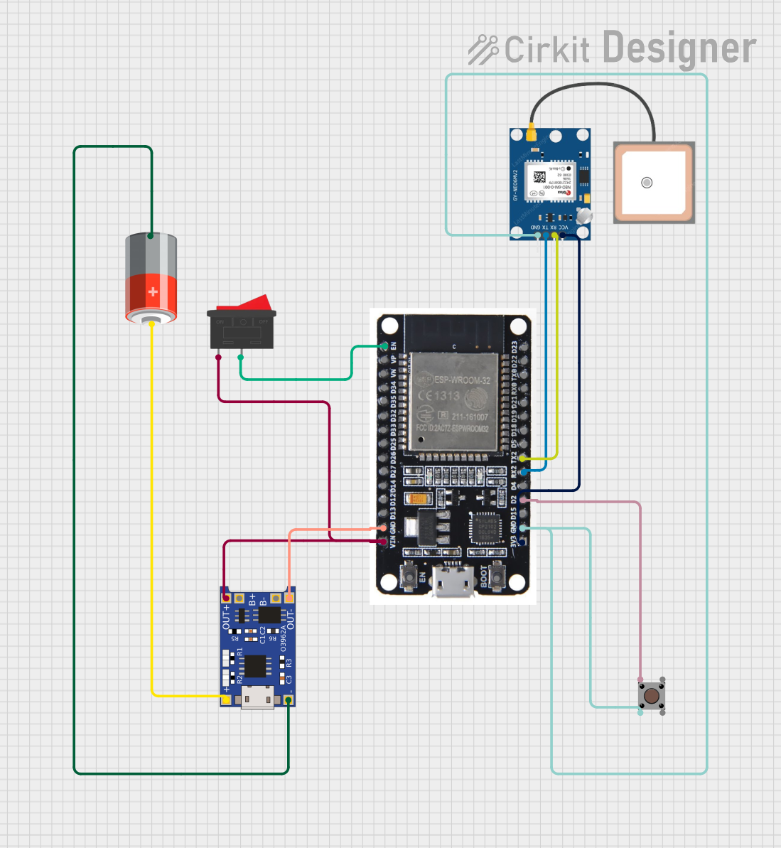
This circuit is designed to interface an ESP32 microcontroller with a GPS NEO 6M module, powered by a 5V battery through a TP4056 charging and protection module. A rocker switch is used to control the power to the ESP32, and a pushbutton is integrated for user input. The ESP32's enable (EN) pin is connected to the rocker switch to allow for manual reset or power cycling. The GPS module is powered by the 3.3V output from the ESP32, and its serial communication lines are connected to the ESP32's RX2 and TX2 pins for data exchange. The pushbutton is connected to one of the ESP32's GPIO pins (D2) for input detection. The battery's voltage is regulated and protected by the TP4056 module, which also provides the charging functionality when connected to an external power source.
Component List
ESP32
- Description: A microcontroller with Wi-Fi and Bluetooth capabilities.
- Pins: EN, VP, VN, D34, D35, D32, D33, D25, D26, D27, D14, D12, D13, GND, VIN, 3V3, D15, D2, D4, RX2, TX2, D5, D18, D19, D21, RX0, TX0, D22, D23, BOOT
GPS NEO 6M
- Description: A GPS module for satellite positioning.
- Pins: VCC, RX, TX, GND
5V Battery
- Description: A power source for the circuit.
- Pins: +, -
TP4056
- Description: A lithium battery charging and protection module.
- Pins: OUT-, B-, B+, OUT+, IN-, IN+
Rocker Switch
- Description: A switch to control the power flow in the circuit.
- Pins: 1, 2
Pushbutton
- Description: A momentary pushbutton for user input.
- Pins: Pin 3 (out), Pin 4 (out), Pin 1 (in), Pin 2 (in)
Wiring Details
ESP32
- EN connected to Rocker Switch pin 2
- GND connected to TP4056 OUT- and Pushbutton Pin 2 (in)
- VIN connected to TP4056 OUT+ through Rocker Switch pin 1
- 3V3 connected to GPS NEO 6M VCC
- D2 connected to Pushbutton Pin 1 (in)
- RX2 connected to GPS NEO 6M TX
- TX2 connected to GPS NEO 6M RX
GPS NEO 6M
- VCC connected to ESP32 3V3
- RX connected to ESP32 TX2
- TX connected to ESP32 RX2
- GND connected to Pushbutton Pin 2 (in)
5V Battery
-
- connected to TP4056 IN+
-
- connected to TP4056 IN-
TP4056
- OUT- connected to ESP32 GND
- OUT+ connected to ESP32 VIN through Rocker Switch
- IN+ connected to 5V Battery +
- IN- connected to 5V Battery -
Rocker Switch
- Pin 1 connected to TP4056 OUT+ and ESP32 VIN
- Pin 2 connected to ESP32 EN
Pushbutton
- Pin 1 (in) connected to ESP32 D2
- Pin 2 (in) connected to ESP32 GND and GPS NEO 6M GND
Documented Code
There is no code provided for the microcontroller in this circuit. The ESP32 would typically be programmed to initialize the serial communication with the GPS module, read and process GPS data, and respond to the pushbutton input. The code would be written in a suitable programming environment, such as the Arduino IDE or ESP-IDF, and uploaded to the ESP32 using a USB-to-serial interface or over-the-air updates if Wi-Fi is configured.