
Arduino UNO Solar-Powered Smart Light System with Wi-Fi Connectivity
View and Edit Project In Cirkit Designer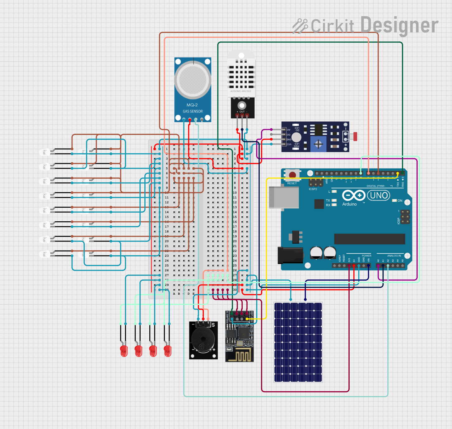
Circuit Documentation
Summary
This circuit involves an Arduino UNO microcontroller interfacing with various sensors, LEDs, a WiFi module, a passive buzzer, and a solar panel. The circuit is designed to collect data from sensors, control LEDs, and communicate wirelessly using the WiFi module. The solar panel provides power to the circuit.
Component List
Arduino UNO
- Description: A microcontroller board based on the ATmega328P.
- Pins: UNUSED, IOREF, Reset, 3.3V, 5V, GND, Vin, A0, A1, A2, A3, A4, A5, SCL, SDA, AREF, D13, D12, D11, D10, D9, D8, D7, D6, D5, D4, D3, D2, D1, D0
Solar Panel
- Description: A device that converts light into electrical energy.
- Pins: +, -
Photoresistor (LDR) Sensor
- Description: A light-dependent resistor used to detect light levels.
- Pins: VCC, GND, DO, AO
WiFi Module ESP8266-01
- Description: A WiFi module used for wireless communication.
- Pins: RX, GPIO0, GPIO2, GND, +3V3, Reset, CH-PD Chip power down, TX
Passive Buzzer
- Description: A device that produces sound when an electrical signal is applied.
- Pins: S output signal, +VCC, GND
DHT22
- Description: A temperature and humidity sensor.
- Pins: +, Out, -
MQ-2
- Description: A gas sensor used to detect various gases.
- Pins: GND, VCC, ANALOG, Digital
LED: Two Pin (white)
- Description: A white LED with two pins.
- Pins: cathode, anode
LED: Two Pin (red)
- Description: A red LED with two pins.
- Pins: cathode, anode
Wiring Details
Arduino UNO
- D5: Connected to the anodes of multiple white LEDs.
- D7: Connected to the S output signal of the Passive Buzzer.
- D8: Connected to the anodes of multiple red LEDs.
- 3.3V: Connected to +3V3, Reset, and CH-PD Chip power down of the WiFi module.
- 5V: Connected to VCC of the Photoresistor, + of the DHT22, VCC of the MQ-2, and +VCC of the Passive Buzzer.
- Vin: Connected to + of the Solar Panel.
- GND: Connected to GND of various components including the WiFi module, LEDs, and sensors.
- A0: Connected to AO of the Photoresistor.
- A1: Connected to Out of the DHT22.
- A2: Connected to ANALOG of the MQ-2.
- D1: Connected to RX of the WiFi module.
- D0: Connected to TX of the WiFi module.
Solar Panel
- +: Connected to Vin of the Arduino UNO.
- -: Connected to GND of the Arduino UNO.
Photoresistor (LDR) Sensor
- VCC: Connected to 5V of the Arduino UNO.
- GND: Connected to GND of the Arduino UNO.
- AO: Connected to A0 of the Arduino UNO.
WiFi Module ESP8266-01
- RX: Connected to D1 of the Arduino UNO.
- TX: Connected to D0 of the Arduino UNO.
- +3V3: Connected to 3.3V of the Arduino UNO.
- GND: Connected to GND of the Arduino UNO.
- Reset: Connected to 3.3V of the Arduino UNO.
- CH-PD Chip power down: Connected to 3.3V of the Arduino UNO.
Passive Buzzer
- S output signal: Connected to D7 of the Arduino UNO.
- +VCC: Connected to 5V of the Arduino UNO.
- GND: Connected to GND of the Arduino UNO.
DHT22
- +: Connected to 5V of the Arduino UNO.
- Out: Connected to A1 of the Arduino UNO.
- -: Connected to GND of the Arduino UNO.
MQ-2
- GND: Connected to GND of the Arduino UNO.
- VCC: Connected to 5V of the Arduino UNO.
- ANALOG: Connected to A2 of the Arduino UNO.
LED: Two Pin (white)
- anode: Connected to D5 of the Arduino UNO.
- cathode: Connected to GND of the Arduino UNO.
LED: Two Pin (red)
- anode: Connected to D8 of the Arduino UNO.
- cathode: Connected to GND of the Arduino UNO.
Documented Code
Arduino UNO Code (sketch.ino)
void setup() {
  // put your setup code here, to run once:

}

void loop() {
  // put your main code here, to run repeatedly:

}
Additional Documentation (documentation.txt)