
ESP8266 NodeMCU Controlled Robotic Vehicle with Ultrasonic Obstacle Detection and Metal Detection
View and Edit Project In Cirkit Designer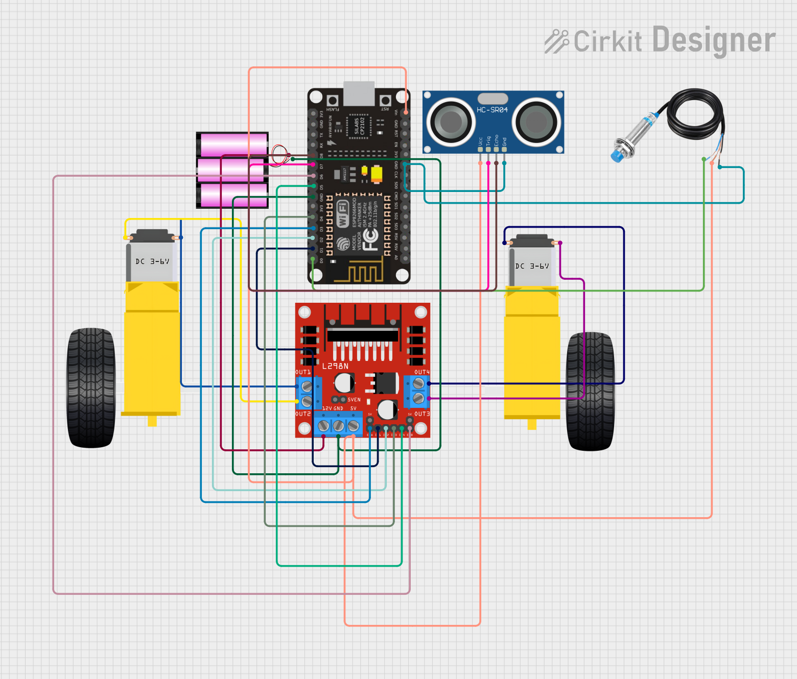
Circuit Documentation
Summary
The circuit described in the provided information is designed to control a pair of DC gearmotors using an ESP8266 NodeMCU microcontroller and an L298N DC motor driver. The circuit also includes a 12V battery for power, an HC-SR04 ultrasonic sensor for distance measurement, and a metal detection sensor for detecting metallic objects. The ESP8266 NodeMCU is responsible for processing sensor inputs and controlling the motor driver, which in turn drives the gearmotors.
Component List
ESP8266 NodeMCU
- Description: A Wi-Fi capable microcontroller module based on the ESP8266 chip.
- Pins: D0, D1, D2, D3, D4, 3V3, GND, D5, D6, D7, D8, RX, TX, A0, RSV, SD3, SD2, SD1, CMD, SD0, CLK, EN, RST, VIN
L298N DC Motor Driver
- Description: A dual H-bridge motor driver module that can control two DC motors.
- Pins: OUT1, OUT2, 12V, GND, 5V, OUT3, OUT4, 5V-ENA-JMP-I, 5V-ENA-JMP-O, +5V-J1, +5V-J2, ENA, IN1, IN2, IN3, IN4, ENB
Gearmotor DC Wheels Left
- Description: A DC gearmotor used to drive the left wheel of a vehicle.
- Pins: PIN1, PIN2
Gearmotor DC Wheels Right
- Description: A DC gearmotor used to drive the right wheel of a vehicle.
- Pins: PIN1, PIN2
Battery 12V
- Description: A 12V battery providing power to the circuit.
- Pins: +, -
HC-SR04 Ultrasonic Sensor
- Description: An ultrasonic sensor used for measuring distances.
- Pins: VCC, TRIG, ECHO, GND
Metal Detection Sensor
- Description: A sensor used to detect the presence of metallic objects.
- Pins: POWER, GND, OUT
Wiring Details
ESP8266 NodeMCU
- D0 connected to Metal Detection Sensor OUT
- D1 connected to L298N DC Motor Driver IN1
- D2 connected to L298N DC Motor Driver IN2
- D3 connected to L298N DC Motor Driver ENA
- D4 connected to L298N DC Motor Driver IN3
- D5 connected to L298N DC Motor Driver IN4
- D6 connected to L298N DC Motor Driver ENB
- D7 connected to HC-SR04 Ultrasonic Sensor TRIG
- D8 connected to HC-SR04 Ultrasonic Sensor ECHO
- GND connected to L298N DC Motor Driver GND, Metal Detection Sensor GND, HC-SR04 Ultrasonic Sensor GND, and Battery 12V -
- VIN connected to Metal Detection Sensor POWER, L298N DC Motor Driver 5V, and HC-SR04 Ultrasonic Sensor VCC
L298N DC Motor Driver
- IN1, IN2, IN3, IN4 connected to ESP8266 NodeMCU D1, D2, D4, D5 respectively
- ENA, ENB connected to ESP8266 NodeMCU D3, D6 respectively
- OUT1, OUT2 connected to Gearmotor DC Wheels Left PIN1, PIN2
- OUT3, OUT4 connected to Gearmotor DC Wheels Right PIN1, PIN2
- 12V connected to Battery 12V +
- GND connected to ESP8266 NodeMCU GND and Battery 12V -
Gearmotor DC Wheels Left
- PIN1 connected to L298N DC Motor Driver OUT1
- PIN2 connected to L298N DC Motor Driver OUT2
Gearmotor DC Wheels Right
- PIN1 connected to L298N DC Motor Driver OUT3
- PIN2 connected to L298N DC Motor Driver OUT4
Battery 12V
-
- connected to L298N DC Motor Driver 12V
-
- connected to L298N DC Motor Driver GND, ESP8266 NodeMCU GND
HC-SR04 Ultrasonic Sensor
- VCC connected to ESP8266 NodeMCU VIN
- TRIG connected to ESP8266 NodeMCU D7
- ECHO connected to ESP8266 NodeMCU D8
- GND connected to ESP8266 NodeMCU GND
Metal Detection Sensor
- POWER connected to ESP8266 NodeMCU VIN
- OUT connected to ESP8266 NodeMCU D0
- GND connected to ESP8266 NodeMCU GND
Documented Code
No code was provided for the microcontroller. The documentation of the code would typically include a description of the functionality, setup, and loop sections, as well as any functions or libraries used. Since no code is available, this section cannot be completed. If code becomes available, it should be documented here with comments explaining the purpose and functionality of each section and line of code.