
Circuit Documentation
Summary
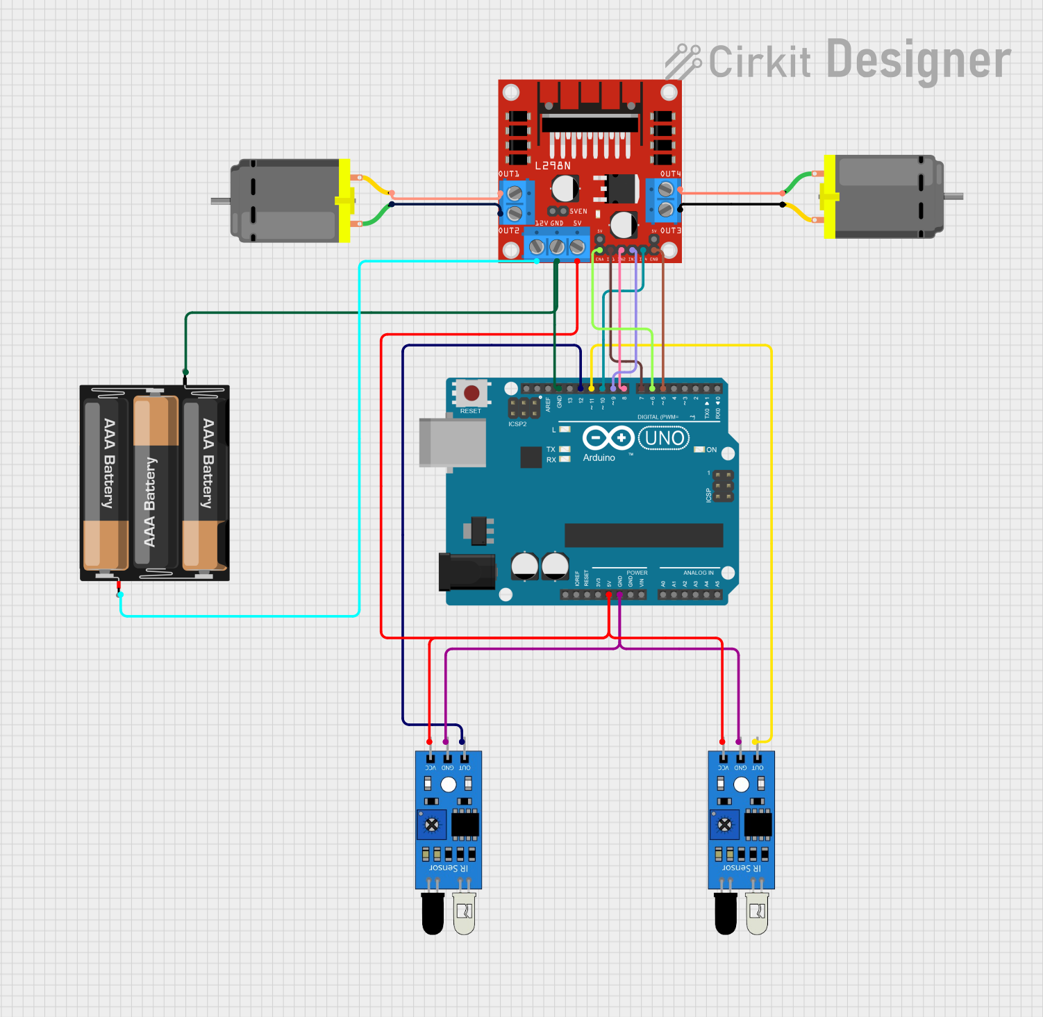
This circuit integrates an Arduino UNO microcontroller with two IR sensors, a L298N DC motor driver, and two DC motors. The circuit is powered by a 3xAA battery pack. The IR sensors are used to detect objects or movements, and their outputs are connected to the Arduino UNO. The L298N motor driver controls the two DC motors based on signals from the Arduino UNO. The battery pack provides power to the motor driver, which in turn powers the motors.
Component List
Arduino UNO
- Microcontroller board based on the ATmega328P
- It has 14 digital input/output pins, 6 analog inputs, a 16 MHz quartz crystal, a USB connection, a power jack, an ICSP header, and a reset button.
IR Sensor (x2)
- An infrared sensor capable of detecting object presence or movement
- It has an output pin that sends a digital signal to the microcontroller.
L298N DC Motor Driver
- A module that can control up to two DC motors with direction and speed control
- It is capable of driving motors with a voltage between 5V and 35V at up to 2A per channel.
DC Motor (x2)
- A simple electric motor that converts electrical energy into mechanical energy
- It has two pins for power connection and can be controlled in terms of speed and direction.
3xAA Battery
- A battery pack consisting of three AA batteries
- It provides a power source for the motor driver and motors.
Wiring Details
Arduino UNO
- 5V: Connected to the 5V pins of both IR sensors and the 5V pin of the L298N motor driver
- GND: Common ground with both IR sensors, the L298N motor driver, and the 3xAA battery pack
- D12: Connected to the output of the first IR sensor
- D11: Connected to the output of the second IR sensor
- D10-D7: Connected to the IN1-IN4 pins of the L298N motor driver for motor control
- D6, D5: Connected to the ENA and ENB pins of the L298N motor driver for enabling motor driver channels
IR Sensor
- VCC: Connected to the 5V output from the Arduino UNO
- GND: Connected to the common ground
- OUT: Connected to either D12 or D11 on the Arduino UNO (depending on the sensor)
L298N DC Motor Driver
- 5V: Connected to the 5V output from the Arduino UNO
- GND: Connected to the common ground
- 12V: Connected to the VCC of the 3xAA battery pack
- IN1-IN4: Controlled by D10-D7 on the Arduino UNO
- ENA, ENB: Controlled by D6, D5 on the Arduino UNO
- OUT1, OUT2: Connected to the first DC motor
- OUT3, OUT4: Connected to the second DC motor
DC Motor
- Pin 1: Connected to either OUT2 or OUT4 on the L298N motor driver
- Pin 2: Connected to either OUT1 or OUT3 on the L298N motor driver
3xAA Battery
- VCC: Connected to the 12V input on the L298N motor driver
- GND: Connected to the common ground
Documented Code
void setup() {
  // put your setup code here, to run once:

}

void loop() {
  // put your main code here, to run repeatedly:

}
The provided code is a template for the Arduino UNO microcontroller. The setup() function is called once when the microcontroller is first powered on or reset. It is used to initialize variables, pin modes, start using libraries, etc. The loop() function is called repeatedly and contains the main logic of the program. This is where the microcontroller will read inputs (such as the IR sensor signals), control outputs (such as the motor driver), and perform other tasks. The actual implementation details need to be filled in based on the specific requirements of the circuit's operation.