Cirkit Designer
Your all-in-one circuit design IDE
Home /
Project Documentation
Arduino-Controlled Dual DC Motor Driver with IR Sensing
Circuit Documentation
Summary
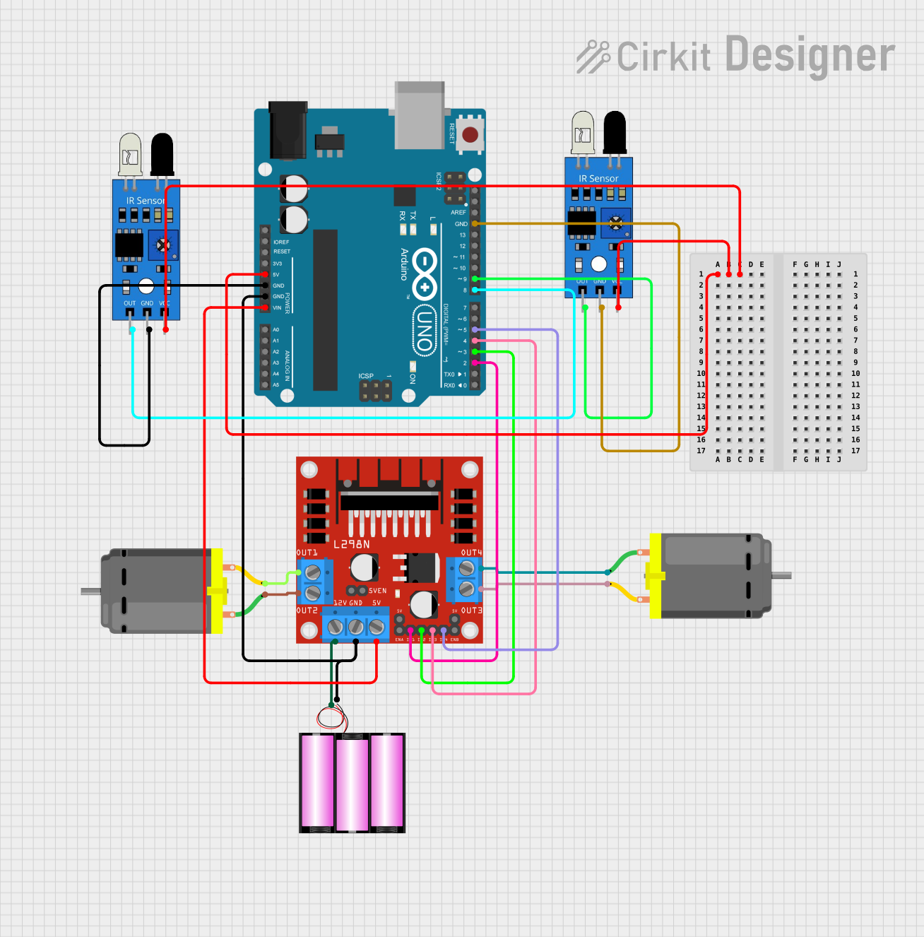
This circuit is designed to control two DC motors using an L298N DC motor driver, which is interfaced with an Arduino UNO microcontroller. The Arduino UNO also connects to two infrared (IR) sensors for input. A 12V battery provides power to the system. The Arduino UNO controls the motor driver by sending signals to its input pins, which in turn drive the motors. The IR sensors are used to provide input signals to the Arduino, which can be programmed to affect the motor operation based on the sensor readings.
Component List
L298N DC Motor Driver
- Description: A motor driver module capable of driving two DC motors.
- Pins: OUT1, OUT2, 12V, GND, 5V, OUT3, OUT4, 5V-ENA-JMP-I, 5V-ENA-JMP-O, +5V-J1, +5V-J2, ENA, IN1, IN2, IN3, IN4, ENB
DC Motor (x2)
- Description: A standard DC motor for rotational motion.
- Pins: pin 1, pin 2
Battery 12V
- Description: A 12-volt battery to provide power to the circuit.
- Pins: +, -
Arduino UNO
- Description: A microcontroller board based on the ATmega328P.
- Pins: UNUSED, IOREF, Reset, 3.3V, 5V, GND, Vin, A0, A1, A2, A3, A4, A5, SCL, SDA, AREF, D13, D12, D11, D10, D9, D8, D7, D6, D5, D4, D3, D2, D1, D0
IR Sensor (x2)
- Description: An infrared sensor for detecting objects and motion.
- Pins: out, gnd, vcc
Wiring Details
L298N DC Motor Driver
- OUT1 connected to DC Motor 1 pin 2
- OUT2 connected to DC Motor 1 pin 1
- OUT3 connected to DC Motor 2 pin 2
- OUT4 connected to DC Motor 2 pin 1
- 12V connected to Battery 12V +
- GND connected to Battery 12V - and Arduino UNO GND
- 5V connected to Arduino UNO Vin
- IN1 connected to Arduino UNO D2
- IN2 connected to Arduino UNO D3
- IN3 connected to Arduino UNO D4
- IN4 connected to Arduino UNO D5
DC Motor 1
- pin 1 connected to L298N DC motor driver OUT2
- pin 2 connected to L298N DC motor driver OUT1
DC Motor 2
- pin 1 connected to L298N DC motor driver OUT4
- pin 2 connected to L298N DC motor driver OUT3
Battery 12V
- connected to L298N DC motor driver 12V
- connected to L298N DC motor driver GND and Arduino UNO GND
Arduino UNO
- GND connected to L298N DC motor driver GND, IR Sensor 1 gnd, IR Sensor 2 gnd, and Battery 12V -
- Vin connected to L298N DC motor driver 5V
- 5V connected to IR Sensor 1 vcc and IR Sensor 2 vcc
- D2 connected to L298N DC motor driver IN1
- D3 connected to L298N DC motor driver IN2
- D4 connected to L298N DC motor driver IN3
- D5 connected to L298N DC motor driver IN4
- D8 connected to IR Sensor 1 out
- D9 connected to IR Sensor 2 out
IR Sensor 1
- out connected to Arduino UNO D8
- gnd connected to Arduino UNO GND
- vcc connected to Arduino UNO 5V
IR Sensor 2
- out connected to Arduino UNO D9
- gnd connected to Arduino UNO GND
- vcc connected to Arduino UNO 5V
Documented Code
Arduino UNO Code (sketch.ino)
void setup() {
  // put your setup code here, to run once:

}

void loop() {
  // put your main code here, to run repeatedly:

}
Note: The provided code is a template and does not contain any functional code to control the motors or read the IR sensors. This will need to be implemented based on the specific requirements of the application.