
STM32F103C8T6-Based Access Control System with RFID and Servo Motor Actuation
View and Edit Project In Cirkit Designer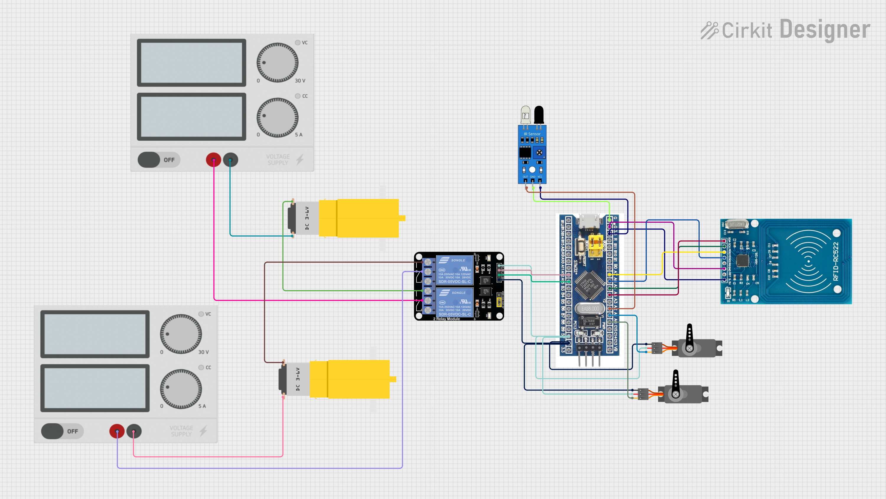
Circuit Documentation
Summary
This circuit integrates various components to perform a set of functions that likely involve sensing, identification, and actuation. The core of the circuit is an STM32F103C8T6 microcontroller, which interfaces with an RFID-RC522 module for RFID reading, two servo motors for actuation, a relay module for controlling power to two hobby motors, and an IR sensor for detecting objects or movements. The power supply units provide the necessary voltage levels to the components.
Component List
RFID-RC522
- Description: An RFID reader module for reading RFID tags.
- Pins: VCC (3.3V), RST, GND, IRQ, MISO, MOSI, SCK, SDA
Servo (x2)
- Description: A motor capable of precise position control.
- Pins: GND, VCC, PWM
STM32F103C8T6
- Description: A 32-bit microcontroller with a range of GPIO pins.
- Pins: GND, 3.3V, reset, B11, B10, B1, B0, A7, A6, A5, A4, A3, A2, A1, A0, C15, C14, C13, VBT, 3.3, 5V, B12, B13, B14, B15, A8, A9, A10, A11, A12, A15, B3, B4, B5, B6, B7, B8, B9, SWIO, SWCLK
Motor Amarillo Motorreductor Hobby (x2)
- Description: A yellow hobby gear motor for general-purpose use.
- Pins: VCC, GND
Relay Module 2 Channel
- Description: A module with two relays to control high power devices.
- Pins: GND, IN1, IN2, VCC, NC1, COM, NO1, NC2, NO2
Power Supply (x2)
- Description: Provides regulated voltage for the circuit.
- Pins: +, -
IR Sensor
- Description: An infrared sensor for object detection.
- Pins: Out, GND, VCC
Wiring Details
RFID-RC522
- VCC (3.3V): Connected to 3.3V of STM32F103C8T6
- GND: Common ground with STM32F103C8T6
- MISO: Connected to A6 of STM32F103C8T6
- MOSI: Connected to A7 of STM32F103C8T6
- SCK: Connected to A5 of STM32F103C8T6
- SDA: Connected to A4 of STM32F103C8T6
Servo (x2)
- GND: Common ground with STM32F103C8T6
- VCC: Connected to 5V of STM32F103C8T6
- PWM: One servo connected to A0 and the other to A1 of STM32F103C8T6
STM32F103C8T6
- GND: Common ground with all GND-connected components
- 3.3V: Supplies power to RFID-RC522 and IR Sensor
- 5V: Supplies power to both Servos and Relay Module 2 Channel
- A0, A1: PWM output to Servos
- A2: Connected to IR Sensor output
- A4, A5, A6, A7: SPI interface with RFID-RC522
- A12, A15: Control signals to Relay Module 2 Channel
Motor Amarillo Motorreductor Hobby (x2)
- VCC: Controlled by Relay Module 2 Channel (NO1 and NO2)
- GND: Connected to the negative terminal of respective Power Supplies
Relay Module 2 Channel
- GND: Common ground with STM32F103C8T6
- VCC: Connected to 5V of STM32F103C8T6
- IN1, IN2: Controlled by A15 and A12 of STM32F103C8T6
- NO1, NO2: Control power to the Motors
- COM: Connected to the positive terminal of Power Supplies
Power Supply (x2)
- +: Supplies power to Motors through Relay Module 2 Channel
- -: Common ground with Motors
IR Sensor
- Out: Connected to A2 of STM32F103C8T6
- GND: Common ground with STM32F103C8T6
- VCC: Connected to 3.3V of STM32F103C8T6
Documented Code
No code was provided for the microcontroller. The documentation of the code would typically include the initialization of peripherals, the main control loop, interrupt service routines, and any other relevant functions or tasks that the microcontroller would perform. This would also include comments explaining the purpose and functionality of the code blocks.