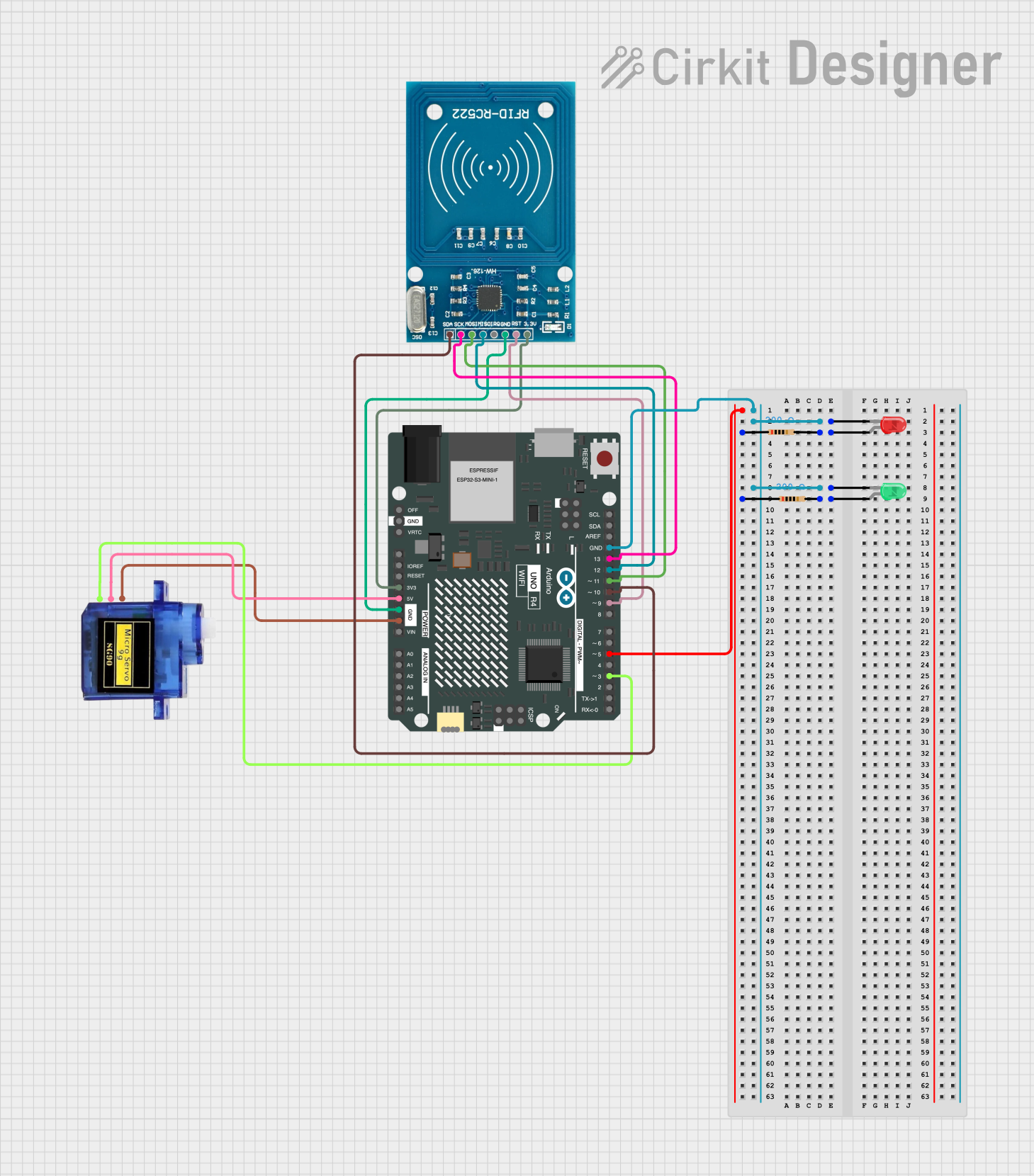
Arduino UNO R4 WiFi Controlled RFID and Servo Interface

Circuit Documentation
Summary
This document provides a detailed overview of a circuit designed to interface an RFID-RC522 module with an Arduino UNO R4 WiFi board. The circuit includes two LEDs (red and green) with current-limiting resistors, and a micro servo 9G for actuation. The Arduino board serves as the central controller, managing the RFID reader and driving the LEDs and servo based on the programmed logic.
Component List
RFID-RC522
- Description: An RFID reader/writer module for contactless communication at 13.56MHz.
- Pins: VCC (3.3V), RST, GND, IRQ, MISO, MOSI, SCK, SDA
LED: Two Pin (red)
- Description: A red LED for indication purposes.
- Pins: cathode, anode
LED: Two Pin (green)
- Description: A green LED for indication purposes.
- Pins: cathode, anode
Micro servo 9G
- Description: A compact and lightweight servo for small-scale projects.
- Pins: GND, +5V, PWM
Resistor (200 Ohms)
- Description: A resistor to limit current to the LEDs.
- Pins: pin1, pin2
- Properties: Resistance: 200 Ohms
Arduino UNO R4 WiFi
- Description: A microcontroller board based on the ATmega328 with integrated WiFi.
- Pins: Multiple GPIOs, power, and analog pins.
Wiring Details
RFID-RC522
- VCC (3.3V) connected to Arduino 3V3
- RST connected to Arduino D9
- GND connected to Arduino GND
- MISO connected to Arduino D12
- MOSI connected to Arduino D11
- SCK connected to Arduino D13
- SDA connected to Arduino D10
LED: Two Pin (red)
- cathode connected to Arduino GND
- anode connected to one end of a 200 Ohm resistor
LED: Two Pin (green)
- cathode connected to Arduino GND
- anode connected to one end of a 200 Ohm resistor
Micro servo 9G
- GND connected to Arduino GND
- +5V connected to Arduino 5V
- PWM connected to Arduino D3
Resistor (200 Ohms)
One end connected to the anode of the red LED
The other end connected to Arduino D5
One end connected to the anode of the green LED
The other end connected to Arduino D5
Documented Code
Arduino UNO R4 WiFi
sketch.ino
void setup() {
  // put your setup code here, to run once:

}

void loop() {
  // put your main code here, to run repeatedly:

}
documentation.txt
(No additional documentation provided for the code)
This concludes the documentation for the given circuit. The code provided is a template and does not include any specific logic for interacting with the RFID-RC522 module, driving the LEDs, or controlling the servo. Users will need to implement the necessary code to create the desired functionality.