
Circuit Documentation
Summary of the Circuit
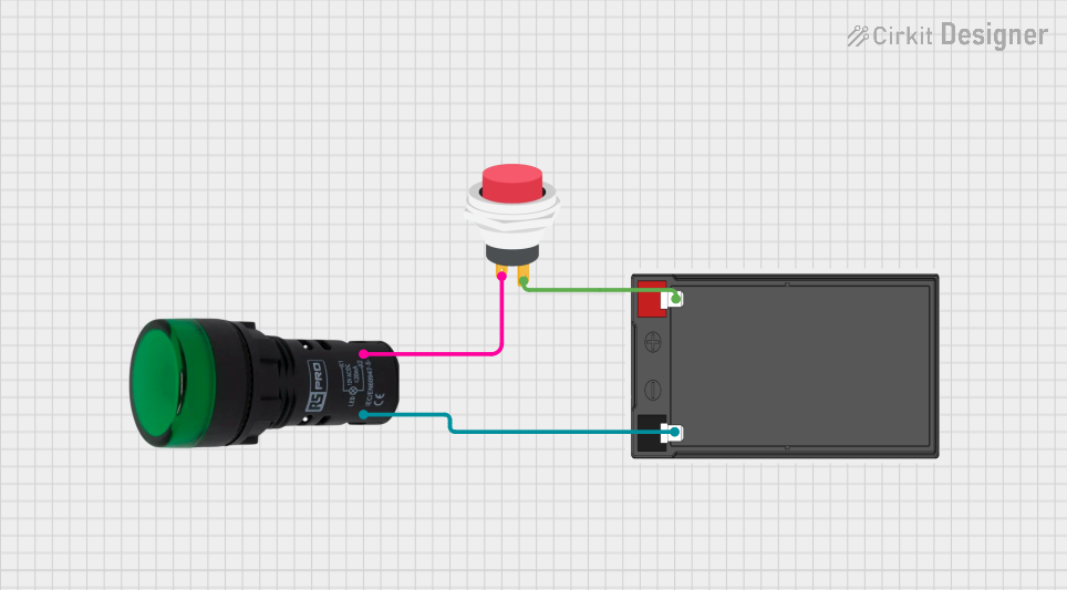
The circuit described by the provided inputs is a simple control circuit that uses a battery to power a green pilot lamp, which is controlled by a 2-pin push switch. When the switch is closed (activated), the circuit is completed, allowing current to flow from the battery through the lamp, causing it to illuminate. The circuit does not include any microcontrollers or complex logic, making it straightforward to understand and implement.
Component List
Pilot Lamp Green
- Description: A green pilot lamp used to indicate the status of the circuit.
- Pins:
- X1: Connection to the negative side of the power source or other components.
- X2: Connection to the switch for controlling the lamp.
Battery
- Description: A power source for the circuit.
- Pins:
- -: Negative terminal of the battery.
- +: Positive terminal of the battery.
2Pin Push Switch
- Description: A simple push-button switch that controls the flow of current.
- Pins:
- Input +: Connection to the positive terminal of the battery or other components.
- Output +: Connection to the load or other components.
Wiring Details
Pilot Lamp Green
- X1: Connected to the negative terminal (-) of the battery.
- X2: Connected to the "Input +" pin of the 2Pin Push Switch.
Battery
- -: Connected to the "X1" pin of the Pilot Lamp Green.
- +: Connected to the "Output +" pin of the 2Pin Push Switch.
2Pin Push Switch
- Input +: Connected to the "X2" pin of the Pilot Lamp Green.
- Output +: Connected to the positive terminal (+) of the battery.
Documented Code
There is no embedded code provided for this circuit as it does not include any microcontrollers or programmable components. The operation of the circuit is purely electrical and mechanical, based on the physical connections and the state of the push switch.