
Circuit Documentation
Summary
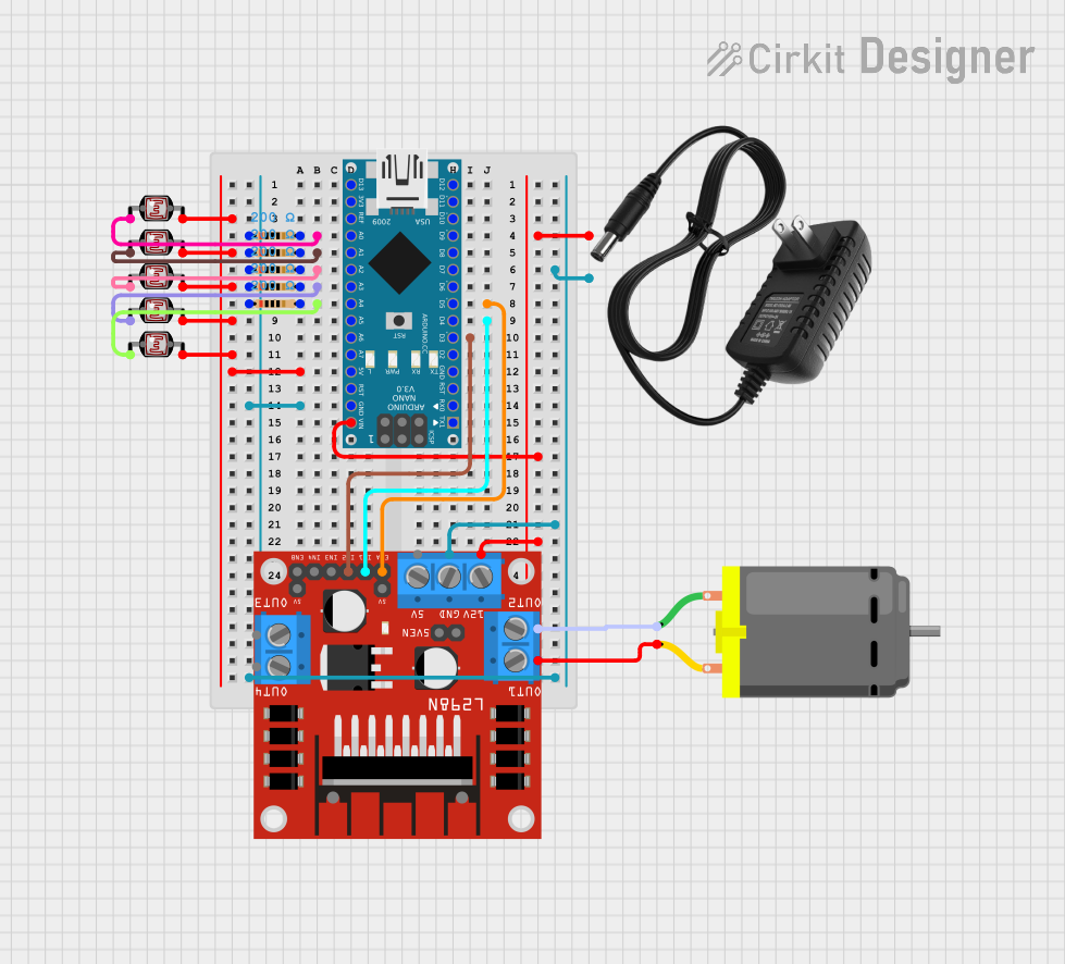
This document provides a detailed overview of a circuit that includes an Arduino Nano microcontroller, an L298N DC motor driver, multiple photocells (LDRs), resistors, a 12V power supply, and a DC motor. The circuit is designed to interface with the Arduino Nano to control the DC motor based on the input from the photocells.
Component List
Arduino Nano
- Description: A small, complete, and breadboard-friendly board based on the ATmega328P.
- Pins: D1/TX, D0/RX, RESET, GND, D2, D3, D4, D5, D6, D7, D8, D9, D10, D11/MOSI, D12/MISO, VIN, 5V, A7, A6, A5, A4, A3, A2, A1, A0, AREF, 3V3, D13/SCK
L298N DC Motor Driver
- Description: A dual H-Bridge motor driver that allows speed and direction control of two DC motors.
- Pins: OUT1, OUT2, 12V, GND, 5V, OUT3, OUT4, 5V-ENA-JMP-I, 5V-ENA-JMP-O, +5V-J1, +5V-J2, ENA, IN1, IN2, IN3, IN4, ENB
Photocell (LDR)
- Description: A light-dependent resistor that changes its resistance based on the light intensity.
- Pins: pin 0, pin 1
12V Power Supply
- Description: Provides a 12V DC output.
- Pins: +, -
Resistor
- Description: A passive electrical component with a resistance of 200 Ohms.
- Pins: pin1, pin2
DC Motor
- Description: A motor that runs on DC power.
- Pins: pin 1, pin 2
Wiring Details
Arduino Nano
- A0: Connected to Resistor (pin2) and Photocell (LDR) (pin 0)
- A1: Connected to Resistor (pin2) and Photocell (LDR) (pin 0)
- A2: Connected to Resistor (pin2) and Photocell (LDR) (pin 0)
- A3: Connected to Resistor (pin2) and Photocell (LDR) (pin 0)
- A4: Connected to Resistor (pin2) and Photocell (LDR) (pin 0)
- D5: Connected to L298N DC motor driver (ENA)
- D4: Connected to L298N DC motor driver (IN1)
- D3: Connected to L298N DC motor driver (IN2)
- 5V: Connected to Photocell (LDR) (pin 1) for all LDRs
- GND: Connected to Resistor (pin1) for all resistors, 12V power supply (-), and L298N DC motor driver (GND)
- VIN: Connected to L298N DC motor driver (OUT1), 12V power supply (+), and L298N DC motor driver (12V)
L298N DC Motor Driver
- ENA: Connected to Arduino Nano (D5)
- IN1: Connected to Arduino Nano (D4)
- IN2: Connected to Arduino Nano (D3)
- GND: Connected to Arduino Nano (GND) and 12V power supply (-)
- OUT1: Connected to Arduino Nano (VIN) and 12V power supply (+)
- 12V: Connected to 12V power supply (+)
- OUT2: Connected to DC Motor (pin 1)
Photocell (LDR)
- pin 0: Connected to Resistor (pin2) and Arduino Nano (A0, A1, A2, A3, A4)
- pin 1: Connected to Arduino Nano (5V)
Resistor
- pin1: Connected to Arduino Nano (GND)
- pin2: Connected to Photocell (LDR) (pin 0) and Arduino Nano (A0, A1, A2, A3, A4)
12V Power Supply
- +: Connected to Arduino Nano (VIN), L298N DC motor driver (OUT1), and L298N DC motor driver (12V)
- -: Connected to Arduino Nano (GND) and L298N DC motor driver (GND)
DC Motor
- pin 1: Connected to L298N DC motor driver (OUT2)
- pin 2: Connected to L298N DC motor driver (OUT1)
Documented Code
Arduino Nano Code (sketch.ino)
void setup() {
  // put your setup code here, to run once:

}

void loop() {
  // put your main code here, to run repeatedly:

}
Additional Documentation (documentation.txt)
This document provides a comprehensive overview of the circuit, including the components used, their connections, and the code running on the Arduino Nano.