Cirkit Designer
Your all-in-one circuit design IDE
Home /
Project Documentation
Arduino Mega 2560-Based RFID and Stepper Motor Control System with I2C LCD Display
Circuit Documentation
Summary
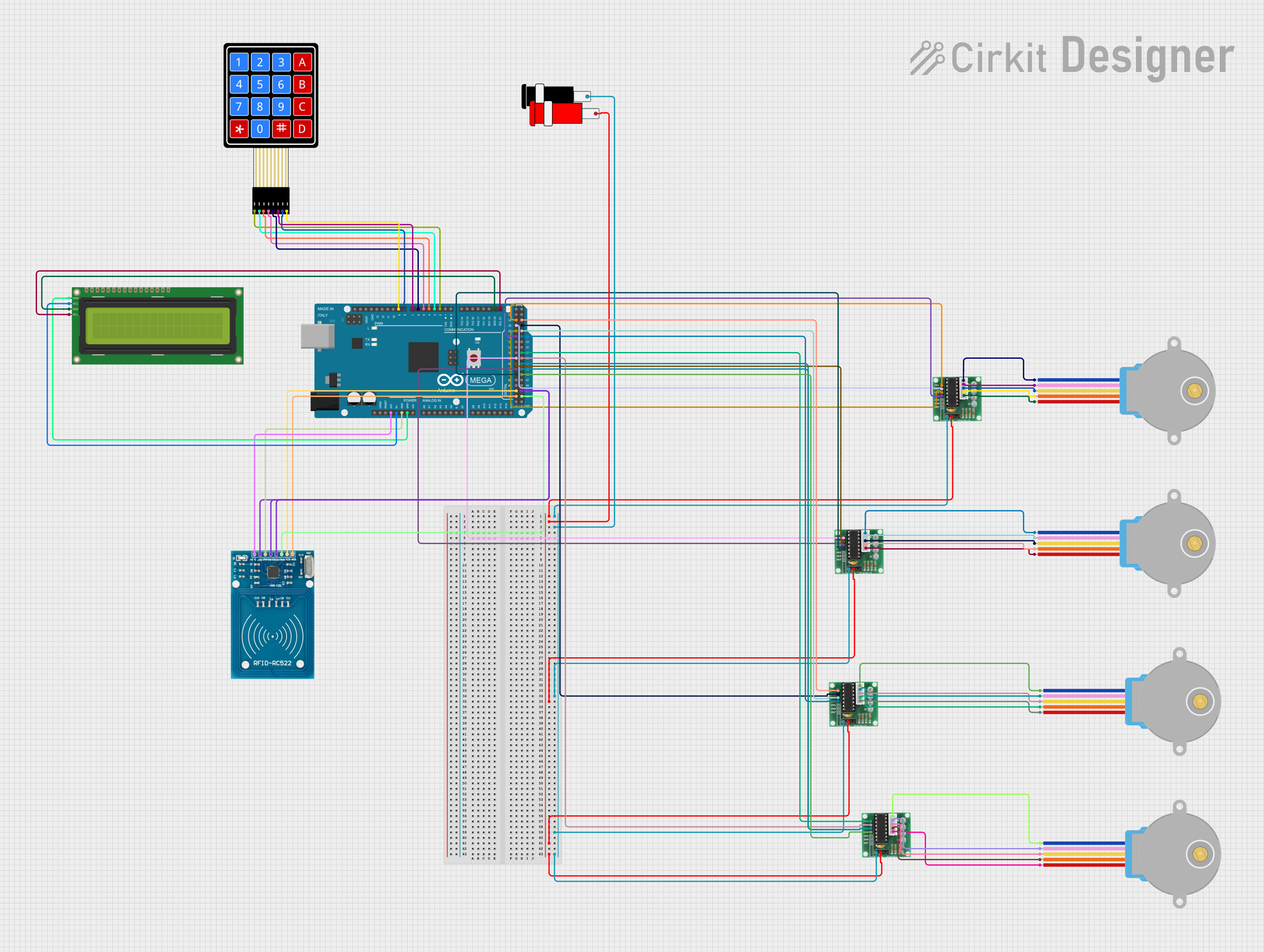
This circuit involves an Arduino Mega 2560 microcontroller interfacing with various components including stepper motors, an I2C LCD, an RFID reader, a membrane keypad, and ULN 2003 motor drivers. The circuit is designed to control multiple stepper motors, display information on an LCD, read RFID tags, and accept input from a keypad.
Component List
Arduino Mega 2560
- Description: A microcontroller board based on the ATmega2560.
- Pins: IOREF, RESET, 3V3, 5V, GND, VIN, A0-A15, D0-D53, AREF, SDA, SCL
28BYJ-48 Stepper Motor
- Description: A small, inexpensive stepper motor.
- Pins: BLUE, PINK, YELLOW, ORANGE, RED
Connector 5V
- Description: A connector providing 5V power.
- Pins: GND, VCC
16x2 I2C LCD
- Description: A 16x2 character LCD with I2C interface.
- Pins: GND, VCC, SDA, SCL
RFID-RC522
- Description: An RFID reader module.
- Pins: VCC (3.3V), RST, GND, IRQ, MISO, MOSI, SCK, SDA
4X4 Membrane Matrix Keypad
- Description: A 4x4 matrix keypad.
- Pins: R1, R2, R3, R4, C1, C2, C3, C4
ULN 2003
- Description: A Darlington transistor array used to drive the stepper motors.
- Pins: IN1-IN7, GND, +, COIL1-COIL5
Wiring Details
Arduino Mega 2560
- 5V to 16x2 I2C LCD VCC
- 3V3 to RFID-RC522 VCC (3.3V)
- GND to 16x2 I2C LCD GND
- GND to RFID-RC522 GND
- D21/SCL to 16x2 I2C LCD SCL
- D20/SDA to 16x2 I2C LCD SDA
- D2 PWM to 4X4 Membrane Matrix Keypad R1
- D3 PWM to 4X4 Membrane Matrix Keypad R2
- D4 PWM to 4X4 Membrane Matrix Keypad R3
- D5 PWM to 4X4 Membrane Matrix Keypad R4
- D6 PWM to 4X4 Membrane Matrix Keypad C1
- D7 PWM to 4X4 Membrane Matrix Keypad C2
- D8 PWM to 4X4 Membrane Matrix Keypad C3
- D9 PWM to 4X4 Membrane Matrix Keypad C4
- D52 to RFID-RC522 SDA
- D50 to RFID-RC522 SCK
- D53 to RFID-RC522 MOSI
- D51 to RFID-RC522 MISO
- D44 to ULN 2003 IN4
- D42 to ULN 2003 IN3
- D40 to ULN 2003 IN2
- D38 to ULN 2003 IN1
- D30 to ULN 2003 IN4
- D28 to ULN 2003 IN3
- D26 to ULN 2003 IN2
- D24 to ULN 2003 IN1
- D45 to ULN 2003 IN4
- D43 to ULN 2003 IN3
- D41 to ULN 2003 IN3
- D39 to ULN 2003 IN2
- D37 to ULN 2003 IN1
- D31 to ULN 2003 IN4
- D29 to ULN 2003 IN3
- D27 to ULN 2003 IN2
- D25 to ULN 2003 IN1
28BYJ-48 Stepper Motor
- BLUE to ULN 2003 COIL1
- PINK to ULN 2003 COIL2
- YELLOW to ULN 2003 COIL3
- ORANGE to ULN 2003 COIL4
- RED to ULN 2003 COIL5
Connector 5V
- VCC to ULN 2003 +
- GND to ULN 2003 GND
16x2 I2C LCD
- VCC to Arduino Mega 2560 5V
- GND to Arduino Mega 2560 GND
- SCL to Arduino Mega 2560 D21/SCL
- SDA to Arduino Mega 2560 D20/SDA
RFID-RC522
- VCC (3.3V) to Arduino Mega 2560 3V3
- GND to Arduino Mega 2560 GND
- SDA to Arduino Mega 2560 D52
- SCK to Arduino Mega 2560 D50
- MOSI to Arduino Mega 2560 D53
- MISO to Arduino Mega 2560 D51
4X4 Membrane Matrix Keypad
- R1 to Arduino Mega 2560 D2 PWM
- R2 to Arduino Mega 2560 D3 PWM
- R3 to Arduino Mega 2560 D4 PWM
- R4 to Arduino Mega 2560 D5 PWM
- C1 to Arduino Mega 2560 D6 PWM
- C2 to Arduino Mega 2560 D7 PWM
- C3 to Arduino Mega 2560 D8 PWM
- C4 to Arduino Mega 2560 D9 PWM
ULN 2003
- + to Connector 5V VCC
- GND to Connector 5V GND
- IN1 to Arduino Mega 2560 D38, D24, D37, D25
- IN2 to Arduino Mega 2560 D40, D26, D39, D27
- IN3 to Arduino Mega 2560 D42, D28, D43, D29
- IN4 to Arduino Mega 2560 D44, D30, D45, D31
- COIL1 to 28BYJ-48 Stepper Motor BLUE
- COIL2 to 28BYJ-48 Stepper Motor PINK
- COIL3 to 28BYJ-48 Stepper Motor YELLOW
- COIL4 to 28BYJ-48 Stepper Motor ORANGE
- COIL5 to 28BYJ-48 Stepper Motor RED
Code Documentation
Arduino Mega 2560 Code
sketch.ino
void setup() {
  // put your setup code here, to run once:

}

void loop() {
  // put your main code here, to run repeatedly:

}
documentation.txt
This documentation provides a comprehensive overview of the circuit, including a summary, detailed component list, wiring details, and the code used in the Arduino Mega 2560 microcontroller.