
ESP8266-Based Smart Door Monitoring System with Color Sensor and Relay Control
View and Edit Project In Cirkit Designer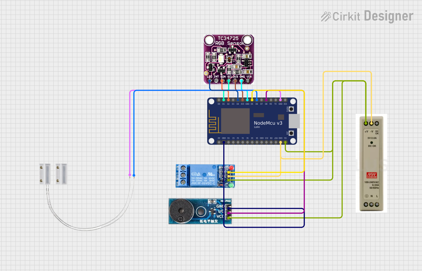
Circuit Documentation
Summary
This circuit is designed to detect the color of an object using a TCS3472 color sensor and trigger a relay and buzzer based on the detected color. The system is controlled by a NodeMCU V3 ESP8266 microcontroller. The circuit also includes a door sensor and a 1-channel relay module. The power supply for the circuit is provided by a 5V PSU.
Component List
1 Channel Relay 5V
- Description: A relay module that allows a low-power microcontroller to control a high-power device.
- Pins: VCC, GND, IN, NC, COM, NO
TCS3472 COLOR LIGHT-TO-DIGITAL CONVERTER with IR FILTER
- Description: A color sensor that converts light to digital values.
- Pins: LED, INT, SDA, SCL, 3V3, GND, VIN
Door MC-38
- Description: A magnetic door sensor used to detect the opening and closing of a door.
- Pins: S, GND
Buzzer Module
- Description: A module that produces sound when activated.
- Pins: GND, Vcc, I/O
NodeMCU V3 ESP8266
- Description: A microcontroller with built-in Wi-Fi capabilities.
- Pins: A0, GND, VU, S3, S2, S1, SC, S0, SK, 3V3, EN, RST, Vin, D0, D1, D2, D3, D4, D5, D6, D7, D8, RX, TX
5V PSU
- Description: A power supply unit that provides 5V DC output.
- Pins: 5V+, GND, 5V OK, PE, N, L
Wiring Details
1 Channel Relay 5V
- VCC connected to 5V+ of 5V PSU
- GND connected to GND of 5V PSU
- IN connected to D5 of NodeMCU V3 ESP8266
TCS3472 COLOR LIGHT-TO-DIGITAL CONVERTER with IR FILTER
- LED connected to D4 of NodeMCU V3 ESP8266
- SDA connected to D2 of NodeMCU V3 ESP8266
- SCL connected to D1 of NodeMCU V3 ESP8266
- 3V3 connected to 3V3 of NodeMCU V3 ESP8266
- GND connected to GND of NodeMCU V3 ESP8266
Door MC-38
- S connected to D6 of NodeMCU V3 ESP8266
- GND connected to GND of NodeMCU V3 ESP8266
Buzzer Module
- Vcc connected to 5V+ of 5V PSU
- GND connected to GND of NodeMCU V3 ESP8266
- I/O connected to D8 of NodeMCU V3 ESP8266
NodeMCU V3 ESP8266
- Vin connected to 5V+ of 5V PSU
- GND connected to GND of 5V PSU
5V PSU
- 5V+ connected to Vin of NodeMCU V3 ESP8266, VCC of 1 Channel Relay 5V, and Vcc of Buzzer Module
- GND connected to GND of NodeMCU V3 ESP8266, GND of 1 Channel Relay 5V, and GND of Buzzer Module
Code Documentation
#include <Wire.h>
#include "Adafruit_TCS34725.h"

Adafruit_TCS34725 tcs = Adafruit_TCS34725(TCS34725_INTEGRATIONTIME_50MS, TCS34725_GAIN_4X);

const int buzzerPin = D8; // Define the buzzer pin
const int relayPin = D6;  // Define the relay pin (corrected from D4 to D6)
const int ledPin = D4;    // Define the LED pin
int brownCount = 0; // Counter for empty canister color detections

void setup() {
    Serial.begin(115200);
    pinMode(buzzerPin, OUTPUT); // Set the buzzer pin as an output
    pinMode(relayPin, OUTPUT);  // Set the relay pin as an output
    pinMode(ledPin, OUTPUT);    // Set the LED pin as an output
    digitalWrite(ledPin, LOW);  // Ensure the LED is off initially
    digitalWrite(relayPin, HIGH); // Ensure the relay is off initially (since it's low-level triggered)

    if (tcs.begin()) {
        Serial.println("Found sensor");
    } else {
        Serial.println("No TCS34725 found, check connections");
        while (1);
    }
}

void loop() {
    uint16_t r, g, b, c, colorTemp, lux;

    // Turn on the LED before reading the sensor
    digitalWrite(ledPin, HIGH);
    delay(500); // Short delay to turn on led
    // Read color data from the sensor
    tcs.getRawData(&r, &g, &b, &c);
    colorTemp = tcs.calculateColorTemperature(r, g, b);
    lux = tcs.calculateLux(r, g, b);

    // Turn off the LED after reading the sensor
    digitalWrite(ledPin, LOW);

    // Print the color data to the serial monitor
    Serial.print("Color Temp: "); Serial.print(colorTemp, DEC); Serial.print(" K - ");
    Serial.print("Lux: "); Serial.print(lux, DEC); Serial.print(" - ");
    Serial.print("R: "); Serial.print(r, DEC); Serial.print(" ");
    Serial.print("G: "); Serial.print(g, DEC); Serial.print(" ");
    Serial.print("B: "); Serial.print(b, DEC); Serial.print(" ");
    Serial.print("C: "); Serial.print(c, DEC); Serial.print(" ");
    Serial.println(" ");

    // Check if the color is brown
    if (isBrown(r, g, b)) {
        brownCount++; // Increment the brown color detection counter

        if (brownCount % 10 == 0) {
            // Trigger the buzzer and relay twice but for a longer duration
            for (int i = 0; i < 2; i++) {
                digitalWrite(buzzerPin, HIGH);
                digitalWrite(relayPin, LOW); // Turn on the relay (low-level triggered)
                delay(1000); // Longer duration
                digitalWrite(buzzerPin, LOW);
                digitalWrite(relayPin, HIGH); // Turn off the relay
                delay(200); // Short delay between beeps
            }
        } else {
            // Trigger the buzzer and relay 3 times
            for (int i = 0; i < 3; i++) {
                digitalWrite(buzzerPin, HIGH);
                digitalWrite(relayPin, LOW); // Turn on the relay (low-level triggered)
                delay(200);
                digitalWrite(buzzerPin, LOW);
                digitalWrite(relayPin, HIGH); // Turn off the relay
                delay(200); // Short delay between beeps
            }
        }
    } else {
        // Trigger the buzzer and relay once
        digitalWrite(buzzerPin, LOW);

        delay(200);
        digitalWrite(buzzerPin, LOW);

    }

    // Wait for 6 second before the next reading
    delay(6000);
}

// Function to determine if the canister is empty
bool isBrown(uint16_t r, uint16_t g, uint16_t b) {
    // Define the range for empty Canister
    // These values might need to be adjusted based on your specific sensor and environment
    return (r > 1000 && r < 2300) && (g > 1100 && g < 2500) && (b > 750 && b < 2000);
}
This code initializes the TCS34725 color sensor and sets up the pins for the buzzer, relay, and LED. In the loop function, it reads the color data from the sensor, checks if the detected color is brown, and triggers the buzzer and relay accordingly. The isBrown function determines if the detected color falls within the specified range for brown.