
Arduino-Based Battery-Powered Water Level Monitoring System with Siren Alert
View and Edit Project In Cirkit Designer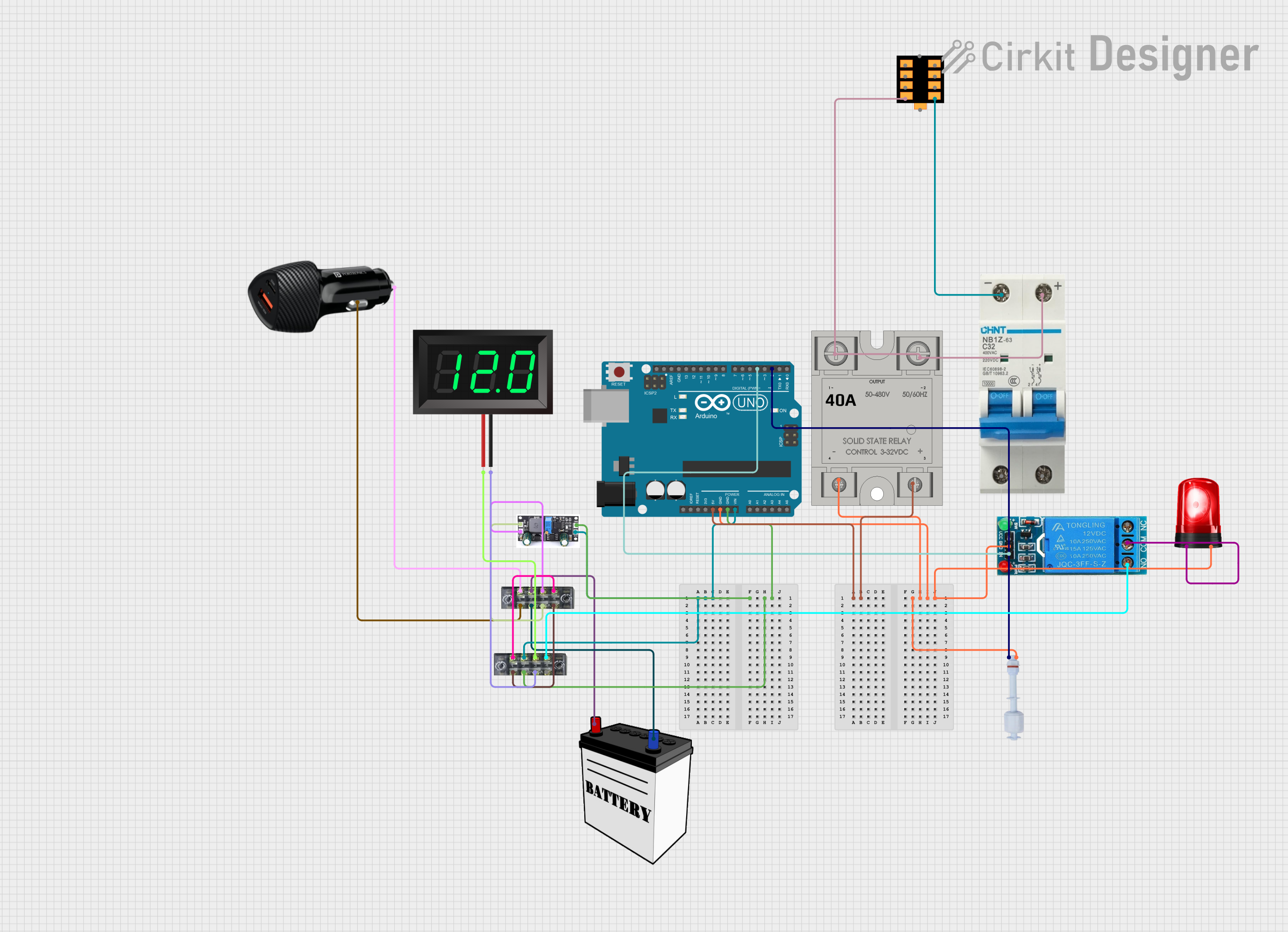
Circuit Documentation
Summary
This document provides a detailed overview of a circuit that includes various components such as relays, a solid-state relay, a float switch, a siren, a power distribution board, a 12V battery, an Arduino UNO, a 7-segment panel voltmeter, a charge controller, and terminal blocks. The circuit is designed to manage power distribution, control a siren based on input from a float switch, and monitor voltage levels.
Component List
SSR-40A
- Description: Solid State Relay
- Pins: -, +, Lin, Lout
- Purpose: Used to control high power devices with low power signals.
12V SINGLE CHANNEL RELAY
- Description: Relay module for switching
- Pins: NC, COM, NO, IN, GND, VCC
- Purpose: Used to control the siren based on signals from the Arduino.
Circuit Breaker
- Description: Safety device to protect the circuit
- Pins: -, +
- Purpose: Provides overcurrent protection.
Power Distribution Board
- Description: Distributes power to various components
- Pins: Power OUT0, Power OUT1, Power OUT2, Power OUT3, Power OUT4, Power OUT5, Power OUT6, Power OUT7, Power OUT8, Power IN
- Purpose: Manages power distribution to different parts of the circuit.
Float Switch
- Description: Water level sensor
- Pins: GND, Digital Pin
- Purpose: Detects water level and sends a signal to the Arduino.
Siren
- Description: Alarm device
- Pins: Positive, Ground
- Purpose: Emits a sound when activated by the relay.
12V Battery
- Description: Power source
- Pins: VCC, GND
- Purpose: Provides power to the circuit.
Arduino UNO
- Description: Microcontroller
- Pins: UNUSED, IOREF, Reset, 3.3V, 5V, GND, Vin, A0, A1, A2, A3, A4, A5, SCL, SDA, AREF, D13, D12, D11, D10, D9, D8, D7, D6, D5, D4, D3, D2, D1, D0
- Purpose: Controls the logic of the circuit.
7-Segment Panel Voltmeter
- Description: Voltage display
- Pins: V+, V-
- Purpose: Displays the voltage level of the battery.
Charge Controller
- Description: Manages battery charging
- Pins: GND, BAT, Vin
- Purpose: Ensures safe charging of the 12V battery.
Terminal Block
- Description: Connection point for wires
- Pins: 1, 2, 3, 4, 5, 6, 7, 8
- Purpose: Provides a convenient way to connect multiple wires.
12 Volt Battery Charger
- Description: Charges the 12V battery
- Pins: -ve, +ve
- Purpose: Provides charging current to the 12V battery.
Wiring Details
SSR-40A
- + connected to Arduino UNO 5V
- - connected to GND (common ground)
- Lin connected to Lout and Power Distribution Board Power OUT3 and Circuit Breaker +
12V SINGLE CHANNEL RELAY
- GND connected to GND (common ground)
- COM connected to Siren Positive
- NO connected to Terminal Block 7
- IN connected to Arduino UNO D4
Circuit Breaker
- + connected to SSR-40A Lin
- - connected to Power Distribution Board Power OUT7
Power Distribution Board
- Power OUT3 connected to SSR-40A Lin
- Power OUT7 connected to Circuit Breaker -
Float Switch
- GND connected to GND (common ground)
- Digital Pin connected to Arduino UNO D2
Siren
- Positive connected to 12V SINGLE CHANNEL RELAY COM
- Ground connected to GND (common ground)
12V Battery
- VCC connected to Terminal Block 3
- GND connected to Terminal Block 4
Arduino UNO
- 5V connected to SSR-40A +
- GND connected to GND (common ground)
- Vin connected to Terminal Block 3
- D2 connected to Float Switch Digital Pin
- D4 connected to 12V SINGLE CHANNEL RELAY IN
7-Segment Panel Voltmeter
- V+ connected to Terminal Block 5
- V- connected to Terminal Block 6
Charge Controller
- Vin connected to Terminal Block 3
- GND connected to Terminal Block 4
- BAT connected to Terminal Block 5
Terminal Block
- 1 connected to 12 Volt Battery Charger +ve
- 2 connected to 12 Volt Battery Charger -ve
- 3 connected to 12V Battery VCC
- 4 connected to 12V Battery GND
- 5 connected to Charge Controller BAT
- 6 connected to Charge Controller GND
- 7 connected to 12V SINGLE CHANNEL RELAY NO
- 8 connected to Terminal Block 2
12 Volt Battery Charger
- +ve connected to Terminal Block 1
- -ve connected to Terminal Block 2
Documented Code
Arduino UNO Code
void setup() {
  // put your setup code here, to run once:

}

void loop() {
  // put your main code here, to run repeatedly:

}
This code is a basic template for the Arduino UNO. The setup() function is where you initialize your settings, and the loop() function is where the main logic of your program runs repeatedly. In this circuit, you would add the logic to read the float switch and control the relay to activate the siren as needed.