
Circuit Documentation
Summary
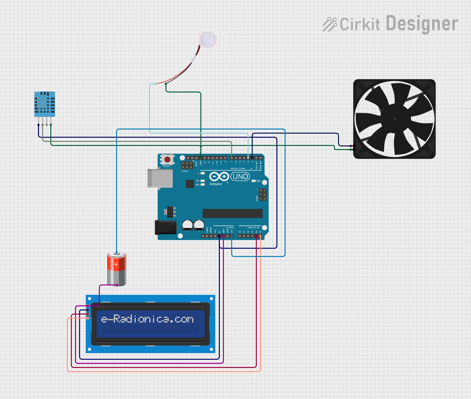
This circuit is designed to control the environmental conditions of a room by maintaining the required temperature and humidity levels. It utilizes an Arduino UNO microcontroller to read temperature and humidity data from a DHT11 sensor and displays these readings on an I2C LCD screen. Based on the sensor data, the Arduino controls a fan and a humidifier to regulate the room's climate. The fan is used to cool down the room when the temperature exceeds a certain threshold, while the humidifier is activated to increase humidity if it falls below a set point.
Component List
Arduino UNO
- Description: A microcontroller board based on the ATmega328P.
- Pins: UNUSED, IOREF, Reset, 3.3V, 5V, GND, Vin, A0-A5, SCL, SDA, AREF, D0-D13.
DHT11 Humidity and Temperature Sensor
- Description: A basic, low-cost digital temperature and humidity sensor.
- Pins: VDD, DATA, NULL, GND.
LCD screen 16x2 I2C
- Description: A 16x2 character LCD display with an I2C interface.
- Pins: SCL, SDA, VCC, GND.
Fan
- Description: An electric fan powered by 5V.
- Pins: GND, 5V.
Humidifier
- Description: A 5V powered humidifier to increase air moisture.
- Pins: GND, 5V.
5v Battery
- Description: A power source providing a 5V output.
- Pins: +, -.
Wiring Details
Arduino UNO
- 5V connected to DHT11 Sensor VDD, LCD screen VCC.
- GND connected to 5v Battery -, DHT11 Sensor GND, LCD screen GND, Fan GND, Humidifier GND.
- Vin connected to 5v Battery +.
- A4 (SDA) connected to LCD screen SDA.
- A5 (SCL) connected to LCD screen SCL.
- D7 connected to DHT11 Sensor DATA.
- D3 connected to Humidifier 5V.
- D2 connected to Fan 5V.
DHT11 Humidity and Temperature Sensor
- VDD connected to Arduino UNO 5V.
- DATA connected to Arduino UNO D7.
- GND connected to Arduino UNO GND.
LCD screen 16x2 I2C
- SCL connected to Arduino UNO A5.
- SDA connected to Arduino UNO A4.
- VCC connected to Arduino UNO 5V.
- GND connected to Arduino UNO GND.
Fan
- 5V connected to Arduino UNO D2.
- GND connected to Arduino UNO GND.
Humidifier
- 5V connected to Arduino UNO D3.
- GND connected to Arduino UNO GND.
5v Battery
- + connected to Arduino UNO Vin.
- - connected to Arduino UNO GND.
Documented Code
/*
 * This Arduino Sketch controls a fan and humidifier to maintain the required
 * temperature and humidity inside a room. It uses a DHT11 sensor to measure
 * temperature and humidity, and an I2C LCD to display the readings. The fan
 * and humidifier are controlled based on the sensor readings.
 */

#include <dht.h>
#include <LiquidCrystal_I2C.h>

LiquidCrystal_I2C lcd(0x27, 16, 2);
dht DHT;

#define DHT11_PIN 7
#define FAN_PIN 2
#define HUMIDIFIER_PIN 3

void setup() {
  lcd.init(); // Initialize I2C LCD
  lcd.backlight(); // Turn on the backlight of the I2C LCD
  pinMode(FAN_PIN, OUTPUT);
  pinMode(HUMIDIFIER_PIN, OUTPUT);
}

void loop() {
  int chk = DHT.read11(DHT11_PIN);
  lcd.setCursor(0, 0);
  lcd.print("Temp: ");
  lcd.print(DHT.temperature);
  lcd.print((char)223);
  lcd.print("C");
  lcd.setCursor(0, 1);
  lcd.print("Humidity: ");
  lcd.print(DHT.humidity);
  lcd.print("%");

  // Control fan based on temperature
  if (DHT.temperature > 25) {
    digitalWrite(FAN_PIN, HIGH); // Turn on fan
  } else {
    digitalWrite(FAN_PIN, LOW); // Turn off fan
  }

  // Control humidifier based on humidity
  if (DHT.humidity < 40) {
    digitalWrite(HUMIDIFIER_PIN, HIGH); // Turn on humidifier
  } else {
    digitalWrite(HUMIDIFIER_PIN, LOW); // Turn off humidifier
  }

  delay(1000); // Wait for 1 second before next reading
}
This code is responsible for initializing the LCD and sensor, reading temperature and humidity data from the DHT11 sensor, displaying the readings on the LCD, and controlling the fan and humidifier based on the sensor data. The fan is turned on when the temperature exceeds 25°C, and the humidifier is activated when the humidity drops below 40%.