
Wi-Fi Controlled Door Monitoring System with NodeMCU and Relay
View and Edit Project In Cirkit Designer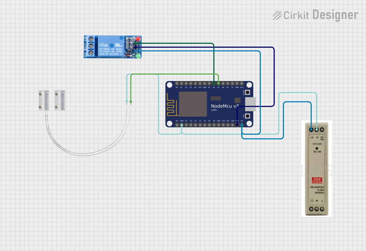
Circuit Documentation
Summary
This circuit is designed to control a relay based on the state of a magnetic door switch using a NodeMCU V3 ESP8266 microcontroller. The relay is activated when the door is closed and deactivated when the door is open. The circuit is powered by a 5V power supply unit (PSU).
Component List
1 Channel Relay 5V
- Description: A relay module that can be controlled by a 5V signal to switch higher power loads.
- Pins: VCC, GND, IN, NC, COM, NO
NodeMCU V3 ESP8266
- Description: A microcontroller with built-in Wi-Fi capabilities, used for controlling the relay and reading the state of the magnetic door switch.
- Pins: A0, GND, VU, S3, S2, S1, SC, S0, SK, 3V3, EN, RST, Vin, D0, D1, D2, D3, D4, D5, D6, D7, D8, RX, TX
5V PSU
- Description: A power supply unit that provides a stable 5V output to power the circuit.
- Pins: 5V+, GND, 5V OK, PE, N, L
Door MC-38
- Description: A magnetic door switch used to detect the open or closed state of a door.
- Pins: S, GND
Wiring Details
1 Channel Relay 5V
- VCC: Connected to 5V+ of the 5V PSU and Vin of the NodeMCU V3 ESP8266.
- GND: Connected to GND of the NodeMCU V3 ESP8266.
- IN: Connected to D6 of the NodeMCU V3 ESP8266.
NodeMCU V3 ESP8266
- Vin: Connected to 5V+ of the 5V PSU and VCC of the 1 Channel Relay 5V.
- GND: Connected to GND of the 5V PSU, GND of the 1 Channel Relay 5V, and GND of the Door MC-38.
- D6: Connected to IN of the 1 Channel Relay 5V.
- D7: Connected to S of the Door MC-38.
5V PSU
- 5V+: Connected to Vin of the NodeMCU V3 ESP8266 and VCC of the 1 Channel Relay 5V.
- GND: Connected to GND of the NodeMCU V3 ESP8266 and GND of the Door MC-38.
Door MC-38
- S: Connected to D7 of the NodeMCU V3 ESP8266.
- GND: Connected to GND of the NodeMCU V3 ESP8266 and GND of the 5V PSU.
Code Documentation
const int relayPin = D6; // Relay In
const int magnet_switch = D7; // Magnet switch
const int debounceDelay = 50; // Debounce delay in milliseconds

void setup() {
  // initialize the relayPin pin as an output:
  pinMode(relayPin, OUTPUT);
  // initialize the magnetic switch pin as an input:
  pinMode(magnet_switch, INPUT_PULLUP);

  Serial.begin(9600);
}

void loop() {
  // Read the initial state of the magnetic switch
  int switchState = digitalRead(magnet_switch);

  // Wait for the debounce delay
  delay(debounceDelay);

  // Read the state of the magnetic switch again
  int switchStateDebounced = digitalRead(magnet_switch);

  // If the state is stable (no bouncing)
  if (switchState == switchStateDebounced) {
    if (switchState == LOW) {
      Serial.println("Switch Closed");
      digitalWrite(relayPin, HIGH); // Relay ON when door is closed
    } else {
      Serial.println("Switch Opened");
      digitalWrite(relayPin, LOW); // Relay OFF when door is opened
    }
  }
}
Code Explanation
- relayPin: Defines the pin connected to the relay module (D6).
- magnet_switch: Defines the pin connected to the magnetic door switch (D7).
- debounceDelay: Sets a delay to debounce the switch input (50 milliseconds).
setup()
- Initializes
relayPinas an output. - Initializes
magnet_switchas an input with an internal pull-up resistor. - Starts the serial communication at 9600 baud rate.
loop()
- Reads the initial state of the magnetic switch.
- Waits for the debounce delay.
- Reads the state of the magnetic switch again.
- If the state is stable (no bouncing):
- If the switch is closed (LOW), the relay is turned ON and a message is printed to the serial monitor.
- If the switch is open (HIGH), the relay is turned OFF and a message is printed to the serial monitor.