Arduino UNO and ESP32 Based Multi-Sensor Environmental Monitoring System with Wi-Fi Connectivity
Circuit Documentation
Summary
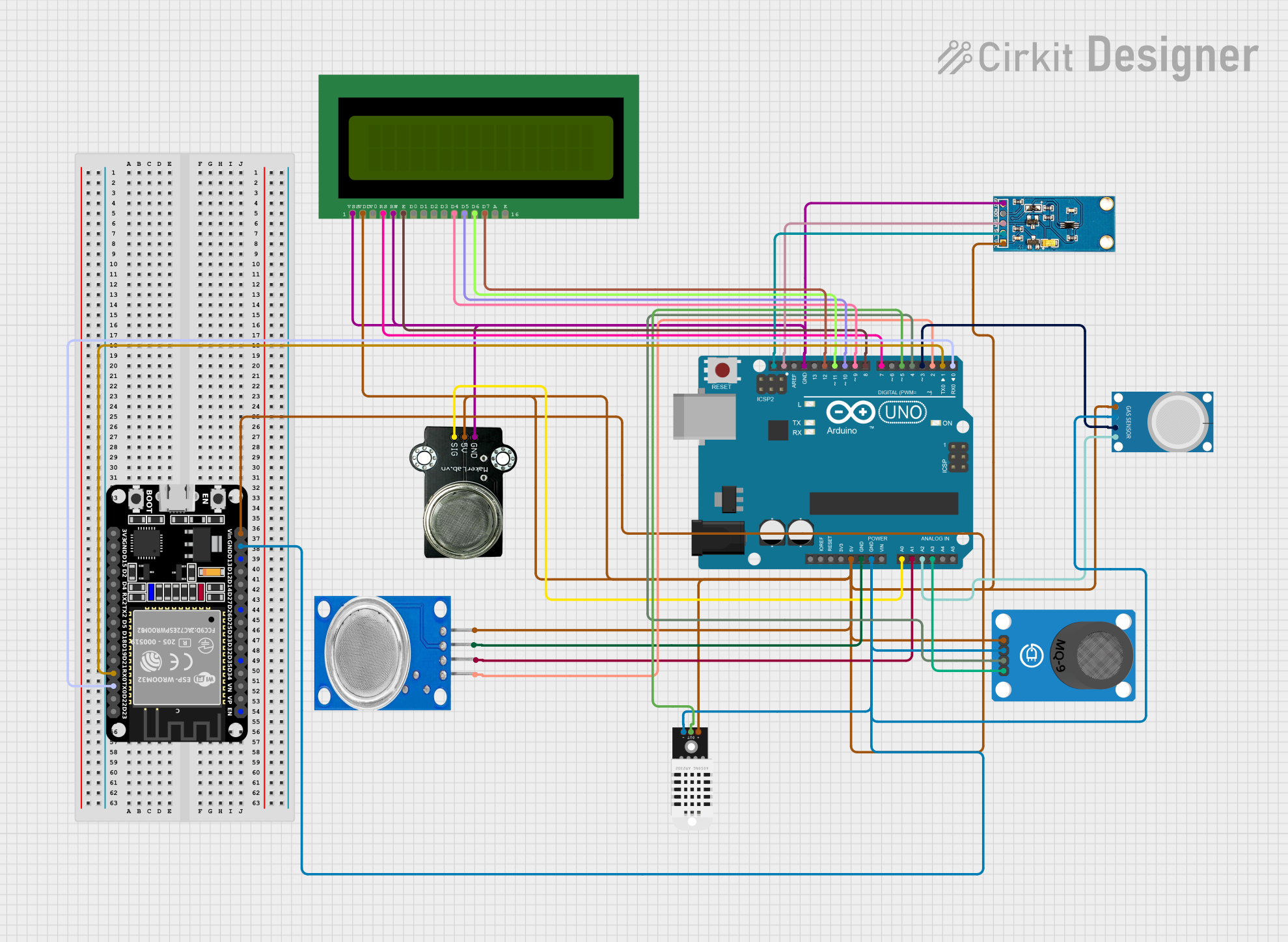
The circuit in question is designed to interface various sensors with an Arduino UNO and an ESP32 microcontroller for data acquisition and processing. The sensors include a light sensor, a DHT22 temperature and humidity sensor, and multiple gas sensors (MQ-4, MQ-9, MQ-135, and MKE-S08 MQ-2). Additionally, a 16x2 LCD display is included for output. The Arduino UNO serves as the central hub for sensor data collection, while the ESP32 is used for additional processing or connectivity.
Component List
Arduino UNO
- Microcontroller board based on the ATmega328P
- It has 14 digital input/output pins, 6 analog inputs, a 16 MHz quartz crystal, a USB connection, a power jack, an ICSP header, and a reset button.
ESP32 (30 pin)
- A powerful microcontroller with Wi-Fi and Bluetooth capabilities
- It has a wide variety of peripherals and is commonly used for IoT projects.
Light Sensor
- A sensor that measures ambient light intensity
- Typically used in applications where it is necessary to adjust brightness based on the surrounding light conditions.
DHT22
- A sensor that measures temperature and humidity
- Known for its reliability and accuracy for environmental monitoring.
MQ-4
- A gas sensor designed for detecting natural gas and methane
- Used in safety systems for gas leak detection.
MQ135
- A sensor for detecting a wide range of gases, including NH3, NOx, alcohol, benzene, smoke, and CO2.
MQ-9 Breakout
- A sensor that detects carbon monoxide and flammable gases
- Suitable for detecting CO and combustible gas concentrations in the air.
MKE-S08 MQ-2 Sensor
- A gas sensor for detecting LPG, propane, hydrogen, and even smoke.
LCD 16x2 (Wokwi Compatible)
- A liquid crystal display capable of displaying 16 characters per line in 2 lines
- Used for displaying sensor data or messages.
Wiring Details
Arduino UNO
5VandGNDpins provide power to the sensors and the LCD.- Analog pins
A0toA3are connected to the gas sensors for analog signal reading. - I2C pins
SCLandSDAare connected to the Light Sensor for communication. - Digital pins
D0toD12are used for interfacing with the ESP32 and the LCD display. - Digital pin
D5is connected to the DHT22 sensor for data output.
ESP32 (30 pin)
VinandGNDare connected to the power rail from the Arduino UNO.RX0andTX0are connected toD0andD1on the Arduino UNO for serial communication.
Light Sensor
VCCandGNDare connected to the power rail.SCLandSDAare connected to the corresponding I2C pins on the Arduino UNO.
DHT22
VCCandGNDare connected to the power rail.OUTis connected to digital pinD5on the Arduino UNO.
MQ-4, MQ135, MQ-9 Breakout, MKE-S08 MQ-2 Sensor
VCCandGNDare connected to the power rail.- Analog output pins are connected to the respective analog pins on the Arduino UNO.
- Digital output pins (if any) are connected to the respective digital pins on the Arduino UNO.
LCD 16x2 (Wokwi Compatible)
VDDandVSSare connected to the power rail.RS,RW,E, and data pinsD4toD7are connected to digital pinsD7toD12on the Arduino UNO.
Documented Code
Arduino UNO Code (sketch.ino)
void setup() {
  // put your setup code here, to run once:

}

void loop() {
  // put your main code here, to run repeatedly:

}
Note: The provided code for the Arduino UNO is a template with empty setup and loop functions. This code should be expanded with initialization of the connected sensors and display, as well as the main logic for reading sensor data and displaying or transmitting it.
ESP32 Code
No code was provided for the ESP32 microcontroller.
End of documentation.