
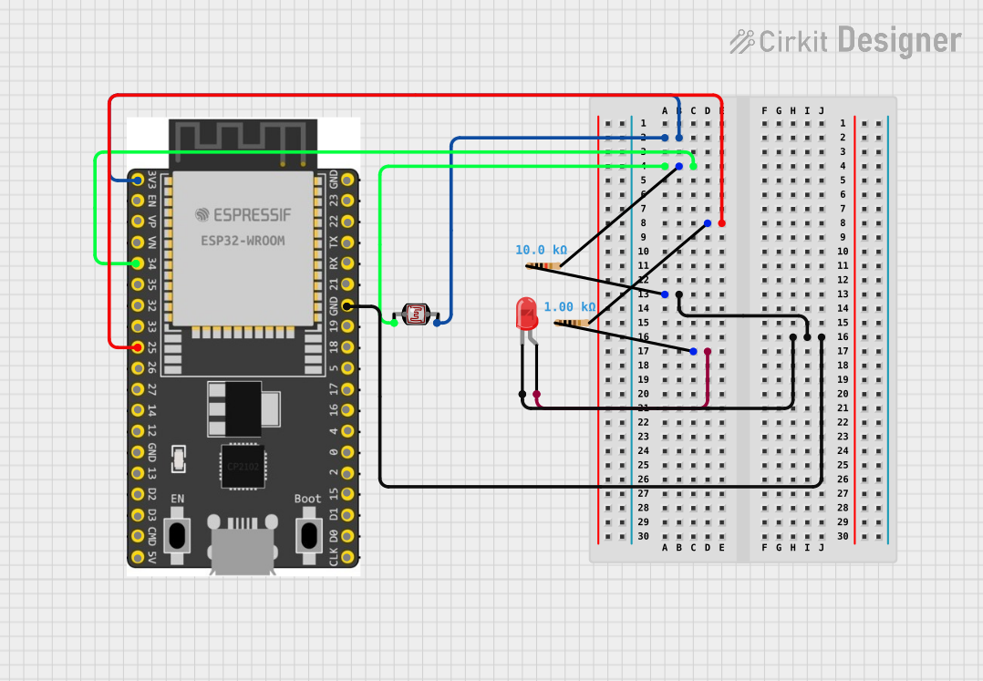
Circuit Documentation
Summary of the Circuit
This circuit is designed around the ESP32 Wroom Dev Kit, which serves as the central processing unit. The circuit includes a photocell (LDR) for light sensing, a red LED as an indicator, and two resistors of different values for voltage division and current limiting purposes. The ESP32 is used to read the analog value from the LDR and control the LED based on certain conditions defined in the embedded code. However, no code has been provided for the microcontroller, indicating that the circuit's logic and behavior are yet to be implemented.
Component List
ESP 32 Wroom Dev Kit
- Description: A development board based on the ESP32 microcontroller with Wi-Fi and Bluetooth capabilities.
- Pins: 3V3, EN, VP, VN, GPIO 34, GPIO 35, GPIO 32, GPIO 33, GPIO 25, GPIO 26, GPIO 27, GPIO 14, GND, GPIO 13, SD2, SD3, CMD, V5, GPIO 23, GPIO 22, TXD, RXD, GPIO 21, GPIO 19, GPIO 18, GPIO 5, GPIO 17, GPIO 16, GPIO 4, GPIO 0, GPIO 2, GPIO 15, SD1, SD0, CLK.
Photocell (LDR)
- Description: A light-dependent resistor whose resistance changes with the intensity of light.
- Pins: pin 0, pin 1.
LED: Two Pin (red)
- Description: A red light-emitting diode used as an indicator.
- Pins: cathode, anode.
Resistor (10k Ohms)
- Description: A resistor with a resistance of 10,000 Ohms, used for voltage division or current limiting.
- Pins: pin1, pin2.
Resistor (1k Ohms)
- Description: A resistor with a resistance of 1,000 Ohms, used for voltage division or current limiting.
- Pins: pin1, pin2.
Wiring Details
ESP 32 Wroom Dev Kit
- 3V3 connected to Photocell (LDR) pin 1.
- GPIO 34 connected to one end of the 10k Ohm Resistor (other end connected to Photocell (LDR) pin 0).
- GPIO 25 connected to one end of the 1k Ohm Resistor (other end connected to LED anode).
- GND connected to the cathode of the LED through a 10k Ohm Resistor.
Photocell (LDR)
- pin 1 connected to 3V3 on the ESP 32 Wroom Dev Kit.
- pin 0 connected to GPIO 34 on the ESP 32 Wroom Dev Kit through a 10k Ohm Resistor.
LED: Two Pin (red)
- cathode connected to GND on the ESP 32 Wroom Dev Kit through a 10k Ohm Resistor.
- anode connected to GPIO 25 on the ESP 32 Wroom Dev Kit through a 1k Ohm Resistor.
Resistor (10k Ohms)
- pin1 connected to GND on the ESP 32 Wroom Dev Kit and to the cathode of the LED.
- pin2 connected to Photocell (LDR) pin 0 and GPIO 34 on the ESP 32 Wroom Dev Kit.
Resistor (1k Ohms)
- pin1 connected to the anode of the LED.
- pin2 connected to GPIO 25 on the ESP 32 Wroom Dev Kit.
Documented Code
No code has been provided for the microcontroller. The expected behavior and logic for the circuit operation should be implemented in the embedded code, which will control the LED based on the analog readings from the LDR. The code should initialize the GPIO pins, set up the ADC for reading the LDR value, and include logic to turn the LED on or off based on predefined light intensity thresholds.