
Arduino UNO-Based Smart Lock System with Fingerprint Scanner and Keypad
View and Edit Project In Cirkit Designer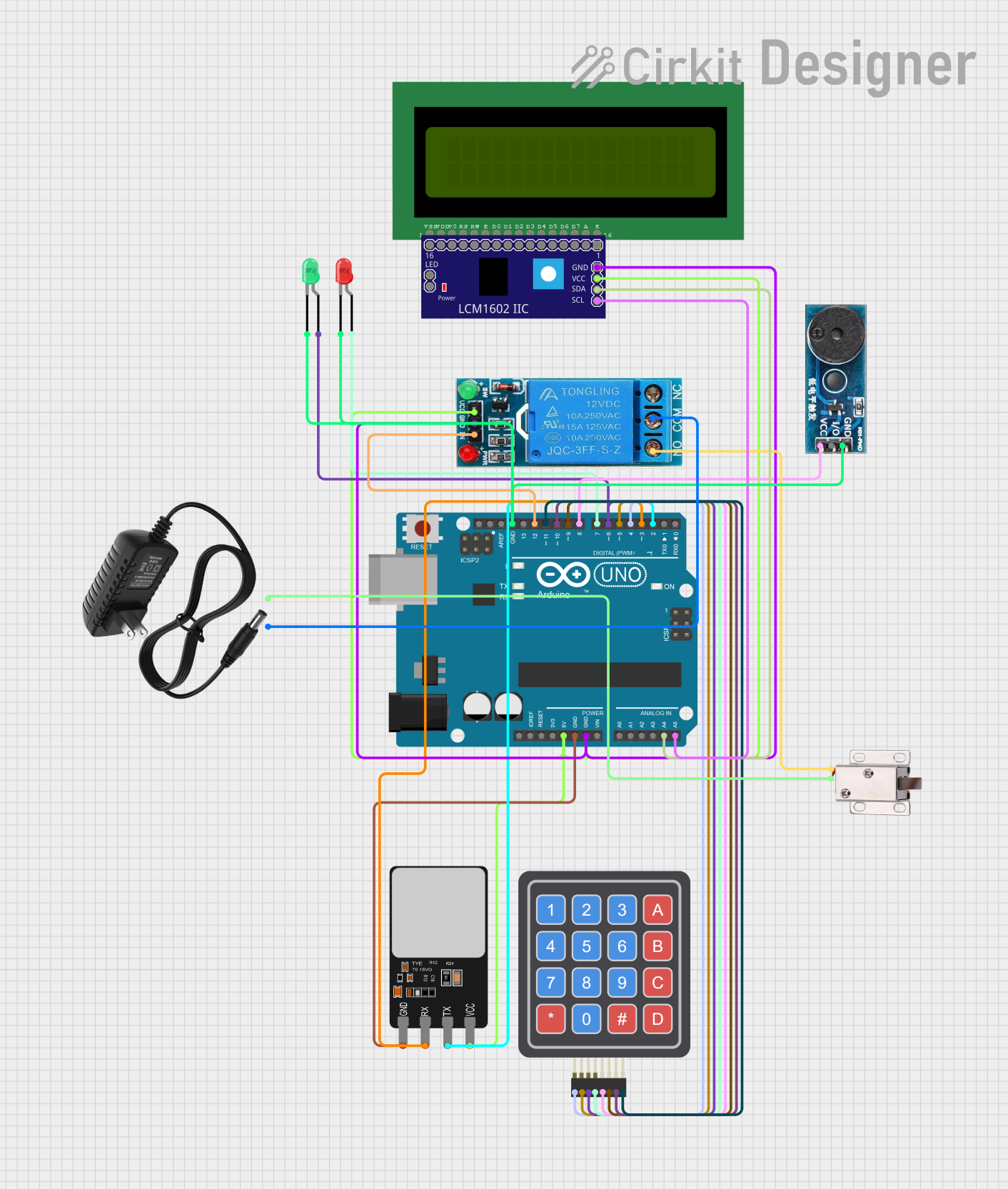
Circuit Documentation
Summary
This circuit is designed to control a 12V solenoid lock using an Arduino UNO. It includes various components such as a fingerprint scanner, a 4x4 keypad, an LCD display, a buzzer module, and LEDs. The Arduino UNO serves as the central microcontroller, interfacing with all other components to manage inputs and outputs.
Component List
Arduino UNO
- Description: Microcontroller board based on the ATmega328P.
- Pins: UNUSED, IOREF, Reset, 3.3V, 5V, GND, Vin, A0, A1, A2, A3, A4, A5, SCL, SDA, AREF, D13, D12, D11, D10, D9, D8, D7, D6, D5, D4, D3, D2, D1, D0
12V Solenoid Lock
- Description: Electromechanical lock that operates on 12V.
- Pins: VCC, GND
12V Single Channel Relay
- Description: Relay module for switching high voltage devices.
- Pins: NC, COM, NO, IN, GND, VCC
12V Power Supply
- Description: Power supply providing 12V output.
- Pins: +, -
Fingerprint Scanner
- Description: Biometric sensor for fingerprint recognition.
- Pins: VCC, TX, RX, GND
Buzzer Module
- Description: Module to produce sound.
- Pins: GND, Vcc, I/O
4x4 Keypad (Simulator)
- Description: Matrix keypad with 4 rows and 4 columns.
- Pins: R1, C4, R2, C2, R3, R4, C1, C3
LCD 16x2 (Wokwi Compatible)
- Description: 16x2 character LCD display.
- Pins: VSS, VDD, V0, RS, RW, E, D0, D1, D2, D3, D4, D5, D6, D7, A, K
LCM1602 IIC
- Description: I2C interface for LCD 1602.
- Pins: GND, VCC, SDA, SCL, D6, D7, A, K, VSS, VDD, V0, RS, D2, D3, D4, D5, RW, E, D0, D1, LED_A, LED_B
LED: Two Pin (Red)
- Description: Red LED with two pins.
- Pins: cathode, anode
LED: Two Pin (Green)
- Description: Green LED with two pins.
- Pins: cathode, anode
Wiring Details
Arduino UNO
5V connected to:
- Fingerprint Scanner (VCC)
- LCM1602 IIC (VCC)
- 12V Single Channel Relay (VCC)
GND connected to:
- Fingerprint Scanner (GND)
- LCM1602 IIC (GND)
- 12V Single Channel Relay (GND)
- Buzzer Module (GND)
- LED: Two Pin (Green) (cathode)
- LED: Two Pin (Red) (cathode)
A4 connected to:
- LCM1602 IIC (SDA)
A5 connected to:
- LCM1602 IIC (SCL)
D12 connected to:
- 12V Single Channel Relay (IN)
D11 connected to:
- 4x4 Keypad (Simulator) (C4)
D10 connected to:
- 4x4 Keypad (Simulator) (C3)
D9 connected to:
- 4x4 Keypad (Simulator) (C2)
D8 connected to:
- 4x4 Keypad (Simulator) (C1)
- Buzzer Module (Vcc)
D7 connected to:
- 4x4 Keypad (Simulator) (R4)
- LED: Two Pin (Red) (anode)
D6 connected to:
- 4x4 Keypad (Simulator) (R3)
- LED: Two Pin (Green) (anode)
D5 connected to:
- 4x4 Keypad (Simulator) (R2)
D4 connected to:
- 4x4 Keypad (Simulator) (R1)
D3 connected to:
- Fingerprint Scanner (RX)
D2 connected to:
- Fingerprint Scanner (TX)
12V Solenoid Lock
VCC connected to:
- 12V Single Channel Relay (NO)
GND connected to:
- 12V Power Supply (-)
12V Single Channel Relay
- COM connected to:
- 12V Power Supply (+)
12V Power Supply
+ connected to:
- 12V Single Channel Relay (COM)
- connected to:
- 12V Solenoid Lock (GND)
Documented Code
Arduino UNO Code (sketch.ino)
void setup() {
  // put your setup code here, to run once:

}

void loop() {
  // put your main code here, to run repeatedly:

}
This code initializes the Arduino UNO and contains empty setup and loop functions. The setup function runs once when the microcontroller is powered on or reset, and the loop function runs continuously after the setup function has completed. You can add your specific logic to these functions to control the connected components.