
Arduino-Based Automated Water Management System with Ultrasonic and Turbidity Sensors
View and Edit Project In Cirkit Designer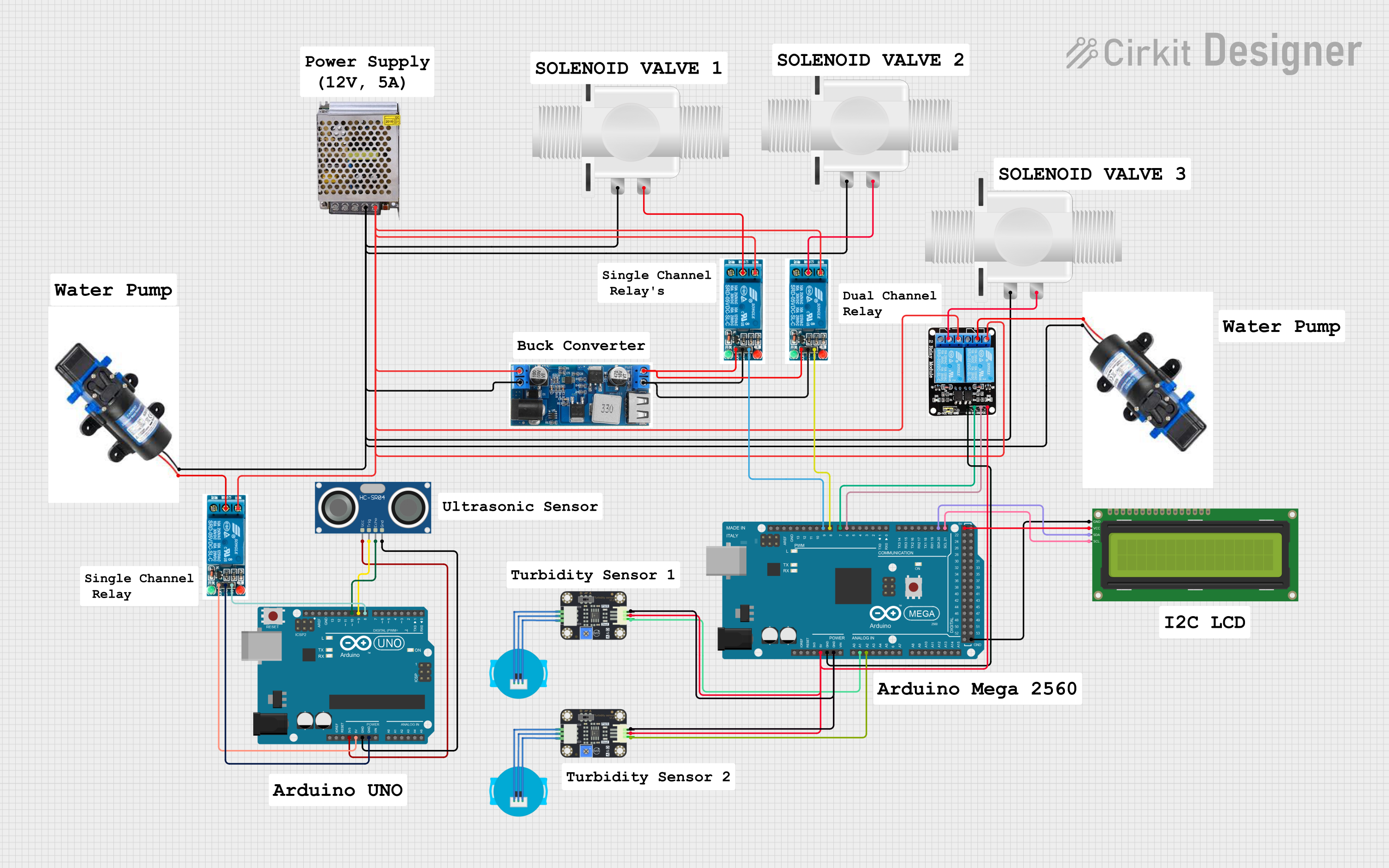
Circuit Documentation
Summary
This document provides a detailed overview of a circuit involving an Arduino UNO, an Arduino Mega 2560, various sensors, relays, and other components. The circuit is designed to interface with multiple sensors and actuators, including ultrasonic sensors, turbidity sensors, solenoid valves, and pumps. The microcontrollers are programmed to control these components based on sensor inputs.
Component List
Arduino UNO
- Description: A microcontroller board based on the ATmega328P.
- Pins: UNUSED, IOREF, Reset, 3.3V, 5V, GND, Vin, A0, A1, A2, A3, A4, A5, SCL, SDA, AREF, D13, D12, D11, D10, D9, D8, D7, D6, D5, D4, D3, D2, D1, D0
HC-SR04 Ultrasonic Sensor
- Description: A sensor used to measure distance using ultrasonic waves.
- Pins: VCC, TRIG, ECHO, GND
5V Relay
- Description: A relay module used to control high voltage devices.
- Pins: Normally Open, Common terminal, Normally Closed, In, GND, VCC
POWER SUPPLY 12V 5AMP
- Description: A power supply providing 12V DC at 5A.
- Pins: 220V Positive Pole (AC), 220V Negative Pole (AC), GND, GND (DC), 12V-24V Output (DC)
Arduino Mega 2560
- Description: A microcontroller board based on the ATmega2560.
- Pins: IOREF, RESET, 3V3, 5V, GND, VIN, A0, A1, A2, A3, A4, A5, A6, A7, A8, A9, A10, A11, A12, A13, A14, A15, D21/SCL, D20/SDA, D19/RX1, D18/TX1, D17 PWM/RX2, D16 PWM/TX2, D15/RX3, D14/TX3, D0 RX0, D1 TX0, D2 PWM, D3 PWM, D4 PWM, D5 PWM, D6 PWM, D7 PWM, D8 PWM, D9 PWM, D10 PWM, D11 PWM, D12 PWM, D13 PWM, AREF, SDA, SCL, D52, D50, D48, D46, D44, D42, D40, D38, D36, D34, D32, D30, D28, D26, D24, D22, D53, D51, D49, D47, D45, D43, D41, D39, D37, D35, D33, D31, D29, D27, D25, D23
5V 2-Relay JD-VCC
- Description: A relay module with two relays.
- Pins: JD-VCC, VCC, GND, IN1, IN2, NO, COM, NC
16x2 I2C LCD
- Description: A 16x2 character LCD with I2C interface.
- Pins: GND, VCC, SDA, SCL
24/12V Buck Converter
- Description: A buck converter to step down voltage.
- Pins: VIN+, VIN-, 5V, GND
Plastic Solenoid Valve
- Description: A valve controlled by an electric current.
- Pins: pin1, pin2
Turbidity Sensor
- Description: A sensor used to measure the turbidity of water.
- Pins: OUT, VCC, GND
Pump
- Description: A device used to move fluids.
- Pins: Pin 2, Pin 1
Wiring Details
Arduino UNO
- 3.3V connected to VCC of HC-SR04 Ultrasonic Sensor
- 5V connected to VCC of 5V Relay
- GND connected to GND of HC-SR04 Ultrasonic Sensor
- GND connected to GND of 5V Relay
- D10 connected to ECHO of HC-SR04 Ultrasonic Sensor
- D9 connected to TRIG of HC-SR04 Ultrasonic Sensor
- D8 connected to In of 5V Relay
HC-SR04 Ultrasonic Sensor
- VCC connected to 3.3V of Arduino UNO
- GND connected to GND of Arduino UNO
- ECHO connected to D10 of Arduino UNO
- TRIG connected to D9 of Arduino UNO
5V Relay
- VCC connected to 5V of Arduino UNO
- GND connected to GND of Arduino UNO
- In connected to D8 of Arduino UNO
- Normally Open connected to Normally Open of another 5V Relay
- Common terminal connected to Pin 1 of Pump
POWER SUPPLY 12V 5AMP
- 12V-24V Output (DC) connected to Normally Open of 5V Relay
- GND (DC) connected to Pin 2 of Pump
Arduino Mega 2560
- 5V connected to VCC of Turbidity Sensor
- GND connected to GND of Turbidity Sensor
- A1 connected to OUT of Turbidity Sensor
- A2 connected to OUT of another Turbidity Sensor
- D21/SCL connected to SCL of 16x2 I2C LCD
- D20/SDA connected to SDA of 16x2 I2C LCD
- D6 PWM connected to IN2 of 5V 2-Relay JD-VCC
- D7 PWM connected to IN1 of 5V 2-Relay JD-VCC
- D8 PWM connected to In of another 5V Relay
- D9 PWM connected to In of another 5V Relay
5V 2-Relay JD-VCC
- VCC connected to 5V of Arduino Mega 2560
- GND connected to GND of Arduino Mega 2560
- IN2 connected to D6 PWM of Arduino Mega 2560
- IN1 connected to D7 PWM of Arduino Mega 2560
- NO connected to Normally Open of 5V Relay
- COM connected to Pin 1 of Pump
16x2 I2C LCD
- VCC connected to 5V of Arduino Mega 2560
- GND connected to GND of Arduino Mega 2560
- SCL connected to D21/SCL of Arduino Mega 2560
- SDA connected to D20/SDA of Arduino Mega 2560
24/12V Buck Converter
- VIN+ connected to Normally Open of 5V Relay
- VIN- connected to Pin 2 of Pump
- 5V connected to VCC of 5V Relay
- GND connected to GND of 5V Relay
Plastic Solenoid Valve
- pin1 connected to Pin 2 of Pump
- pin2 connected to Common terminal of 5V Relay
Turbidity Sensor
- VCC connected to 5V of Arduino Mega 2560
- GND connected to GND of Arduino Mega 2560
- OUT connected to A1 of Arduino Mega 2560
Pump
- Pin 1 connected to Common terminal of 5V Relay
- Pin 2 connected to VIN- of 24/12V Buck Converter
Documented Code
Arduino UNO Code
void setup() {
  // put your setup code here, to run once:

}

void loop() {
  // put your main code here, to run repeatedly:

}
Arduino Mega 2560 Code
void setup() {
  // put your setup code here, to run once:

}

void loop() {
  // put your main code here, to run repeatedly:

}
This documentation provides a comprehensive