
ESP32-Based Environmental Monitoring and Alert System with Solar Charging
View and Edit Project In Cirkit Designer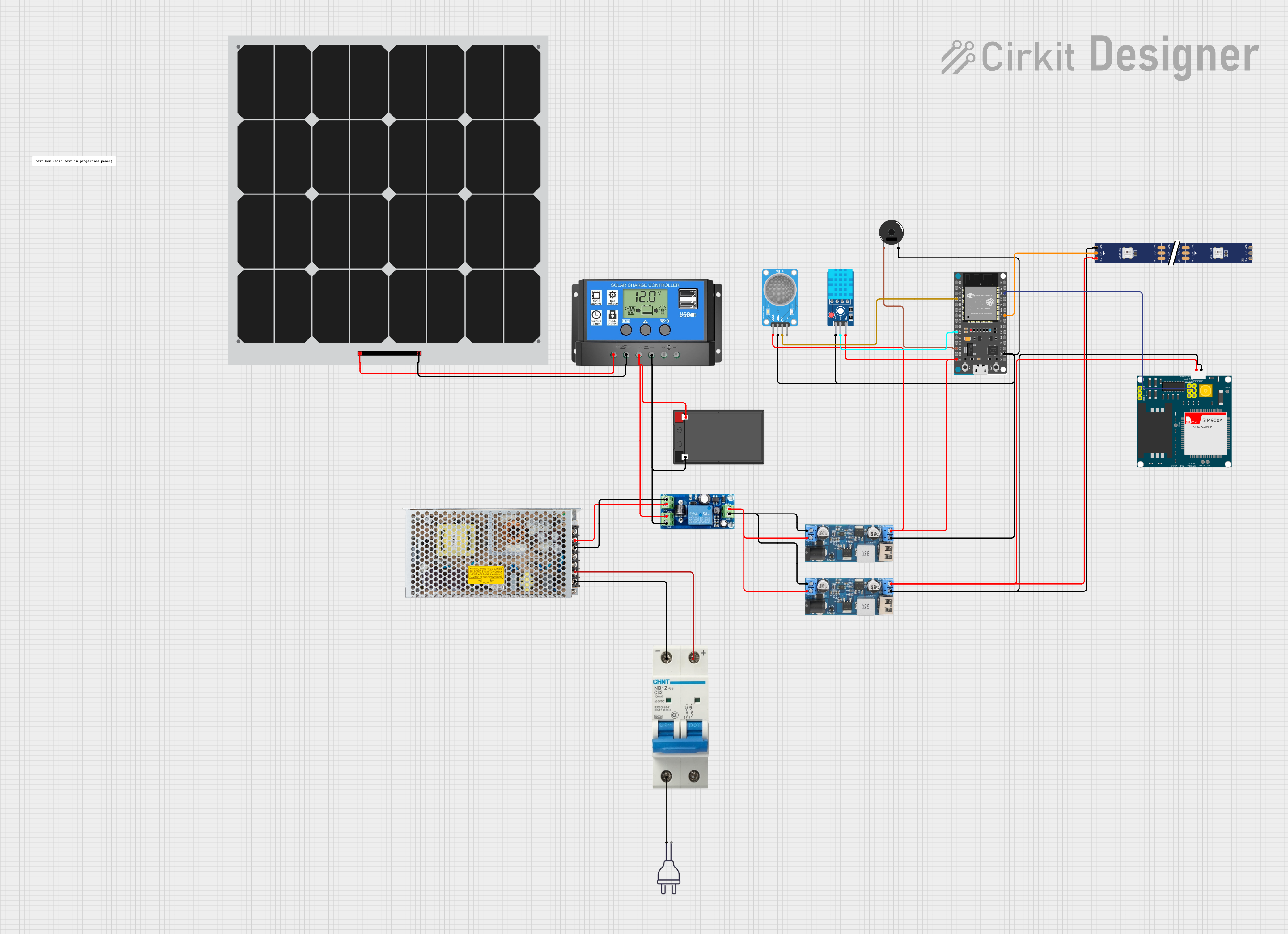
Circuit Documentation
Summary
The circuit in question is a complex system designed to integrate various sensors, power management modules, a microcontroller, and communication modules. The primary controller of the circuit is an ESP32 Devkit V1, which interfaces with a DHT11 temperature and humidity sensor, an MQ-2 gas sensor, and a WS2812 RGB LED strip. The circuit also includes power management components such as a UPS module, step-down power converters, a solar charge controller, and a switching power supply to maintain a stable power supply for all components. Additionally, a SIM900A module is included for cellular communication capabilities. A piezo buzzer provides audio feedback, and a circuit breaker is included for overcurrent protection. The entire system is powered by a combination of a solar panel and a 12V battery, ensuring continuous operation.
Component List
ESP32 Devkit V1
- Microcontroller with WiFi and Bluetooth capabilities.
- Pins: 3V3, GND, D15, D2, D4, RX2, TX2, D5, D18, D19, D21, RX0, TX0, D22, D23, EN, VP, VN, D34, D35, D32, D33, D25, D26, D27, D14, D12, D13, VIN.
WS2812 RGB LED Strip
- A strip of addressable RGB LEDs.
- Pins: DIN, 5V, GND, DO.
MQ-2 Gas Sensor
- A sensor for detecting flammable gases and smoke.
- Pins: VCC, GND, A0, D0.
DHT11 Sensor V2
- A sensor for measuring temperature and humidity.
- Pins: GND, DAT, VCC.
UPS Module
- An uninterruptible power supply module for power backup.
- Pins: DC-, DC+, BAT+, BAT-, OUT+, OUT-.
12V to 5V Step Down Power Converter
- A module to convert 12V to 5V.
- Pins: VIN 9v-36v, VIN+, VIN-, USB OUTPUT 5V, 5v OUTPUT, GND.
12V 7Ah Battery
- A rechargeable battery providing 12V output.
- Pins: 12v +, 12v -.
Solar Charge Controller
- A controller for charging the battery from a solar panel.
- Pins: Solar Cell +, Solar Cell -, Battery +, Battery -, Load +, Load -.
Solar Panel
- A photovoltaic panel for converting solar energy into electrical energy.
- Pins: +, -.
Switching Power Supply
- A power supply unit for converting AC to DC voltage.
- Pins: AC, GND, -V, +V.
Piezo Buzzer
- An electronic buzzer for audio alerts.
- Pins: pin 1, pin 2.
SIM900A
- A GSM/GPRS module for cellular communication.
- Pins: GND, DB9-3 (RXD), DB9-2 (TXD), 5V, 3VR, 5VR, 3VT, 5VT, VCC, Ring, RESTART, RESET, STATUS.
Circuit Breaker
- A safety device to protect the circuit from overcurrent.
- Pins: -, +.
Power 220V
- The main power source for the circuit.
- Pins: hot wire, neutral wire.
Wiring Details
ESP32 Devkit V1 Wiring
- GND connected to DHT11 Sensor V2 (GND), MQ-2 Sensor (GND), Piezo Buzzer (pin 2), and 12V to 5V Step Down Power Converter (GND).
- D18 connected to WS2812 RGB LED Strip (DIN).
- TX0 connected to SIM900A (5VR).
- D34 connected to MQ-2 Sensor (A0).
- D27 connected to DHT11 Sensor V2 (DAT).
- D13 connected to Piezo Buzzer (pin 1).
- VIN connected to DHT11 Sensor V2 (VCC), 12V to 5V Step Down Power Converter (5v OUTPUT), and MQ-2 Sensor (VCC).
WS2812 RGB LED Strip Wiring
- DIN connected to ESP32 Devkit V1 (D18).
- 5V and GND connected to 12V to 5V Step Down Power Converter (5v OUTPUT and GND).
MQ-2 Sensor Wiring
- VCC and GND connected to ESP32 Devkit V1 (VIN and GND).
- A0 connected to ESP32 Devkit V1 (D34).
DHT11 Sensor V2 Wiring
- GND and VCC connected to ESP32 Devkit V1 (GND and VIN).
- DAT connected to ESP32 Devkit V1 (D27).
UPS Module Wiring
- DC- and DC+ connected to Switching Power Supply (-V and +V).
- BAT- and BAT+ connected to 12V 7Ah Battery (12v - and 12v +).
- OUT- and OUT+ connected to 12V to 5V Step Down Power Converter (VIN- and VIN+).
12V to 5V Step Down Power Converter Wiring
- 5v OUTPUT and GND connected to ESP32 Devkit V1 (VIN and GND), SIM900A (5V and GND), and WS2812 RGB LED Strip (5V and GND).
- VIN+ and VIN- connected to UPS Module (OUT+ and OUT-).
Solar Charge Controller Wiring
- Solar Cell + and Solar Cell - connected to Solar Panel (+ and -).
- Battery + and Battery - connected to 12V 7Ah Battery (12v + and 12v -).
Switching Power Supply Wiring
- AC connected to Circuit Breaker (- and +).
Piezo Buzzer Wiring
- Pin 1 and pin 2 connected to ESP32 Devkit V1 (D13 and GND).
SIM900A Wiring
- 5V and GND connected to 12V to 5V Step Down Power Converter (5v OUTPUT and GND).
- 5VR connected to ESP32 Devkit V1 (TX0).
Documented Code
No code was provided for the microcontrollers in the circuit. Therefore, this section is left blank until the relevant code is made available.