
Circuit Documentation
Summary of the Circuit
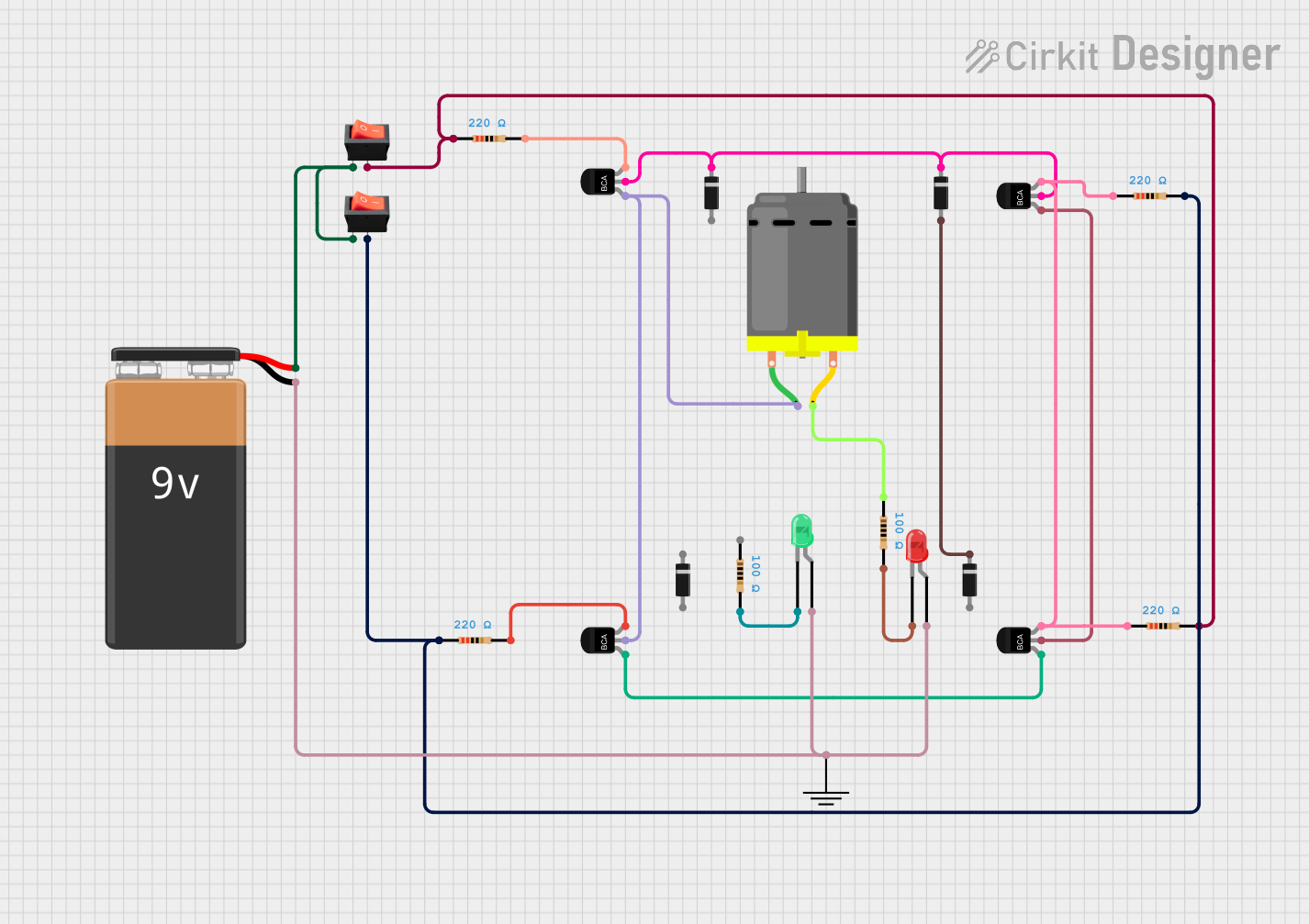
This circuit appears to be a control system for a DC motor with an integrated LED indicator system. The circuit includes a 9V battery as the power source, rocker switches for controlling the power flow, resistors for current limiting, NPN transistors as switches or amplifiers, diodes for directional current flow, a DC motor as the load, and LEDs as visual indicators. The circuit does not include any microcontroller code, suggesting that the operation is purely hardware-based without programmable control logic.
Component List
Diode
- Description: A semiconductor device that allows current to flow in one direction only.
- Purpose: Typically used for protecting sensitive components from reverse voltage or for rectifying AC to DC.
DC Motor
- Description: An electric motor that runs on direct current (DC) electricity.
- Purpose: Acts as the primary load in the circuit, converting electrical energy into mechanical motion.
NPN-Transistor
- Description: A type of bipolar junction transistor (BJT) with one P-type and two N-type materials.
- Purpose: Used as a switch or amplifier in electronic circuits.
LED: Two Pin (red/green)
- Description: A light-emitting diode that emits red or green light when forward-biased.
- Purpose: Serves as an indicator light in the circuit.
Resistor
- Description: A passive two-terminal electrical component that implements electrical resistance as a circuit element.
- Purpose: Used to limit current, divide voltages, and for biasing active elements.
Rocker Switch
- Description: A switch that rocks back and forth when pressed, with one side of the switch raised while the other side is depressed.
- Purpose: Used to open or close the circuit, controlling the flow of current.
9V Battery
- Description: A standard size of battery typically used in small electronic devices.
- Purpose: Provides the power source for the circuit.
GND
- Description: A reference point in an electrical circuit from which voltages are measured, a common return path for electric current, or a direct physical connection to the Earth.
- Purpose: Acts as the common ground reference for the circuit.
Wiring Details
Diode
- Anode connected to the positive side of the circuit or other components as required.
- Cathode connected to the negative side or towards other components to ensure correct current flow.
DC Motor
- One pin connected to the collector of an NPN transistor for controlled operation.
- The other pin connected to a resistor or directly to the power source depending on the desired motor speed and current requirements.
NPN-Transistor
- Emitter (E) typically connected to ground or negative side of the power source.
- Base (B) connected to a control signal or a resistor for biasing.
- Collector (C) connected to the load or next stage in the circuit.
LED: Two Pin (red/green)
- Anode connected to the positive side of the circuit, often through a current-limiting resistor.
- Cathode connected to the negative side or ground.
Resistor
- Connected in series with LEDs, transistors, or other components to limit current or drop voltage as required.
Rocker Switch
- One pin connected to the power source.
- The other pin connected to the load or next stage in the circuit to control power flow.
9V Battery
- Positive (+) terminal connected to switches, resistors, or directly to components requiring power.
- Negative (-) terminal connected to ground or the negative side of the circuit.
GND
- All ground connections in the circuit are tied to this common point.
Documented Code
No code has been provided for this circuit. The operation is controlled through hardware components without the need for embedded software.
Please note that the above documentation is based on the provided information and assumes typical connections for the components listed. Without a schematic or further details on the intended operation of the circuit, some assumptions have been made regarding the purpose and interconnections of the components.