
Arduino UNO Bluetooth-Controlled Robot with Traffic Light Indicator and Servo Actuation
View and Edit Project In Cirkit Designer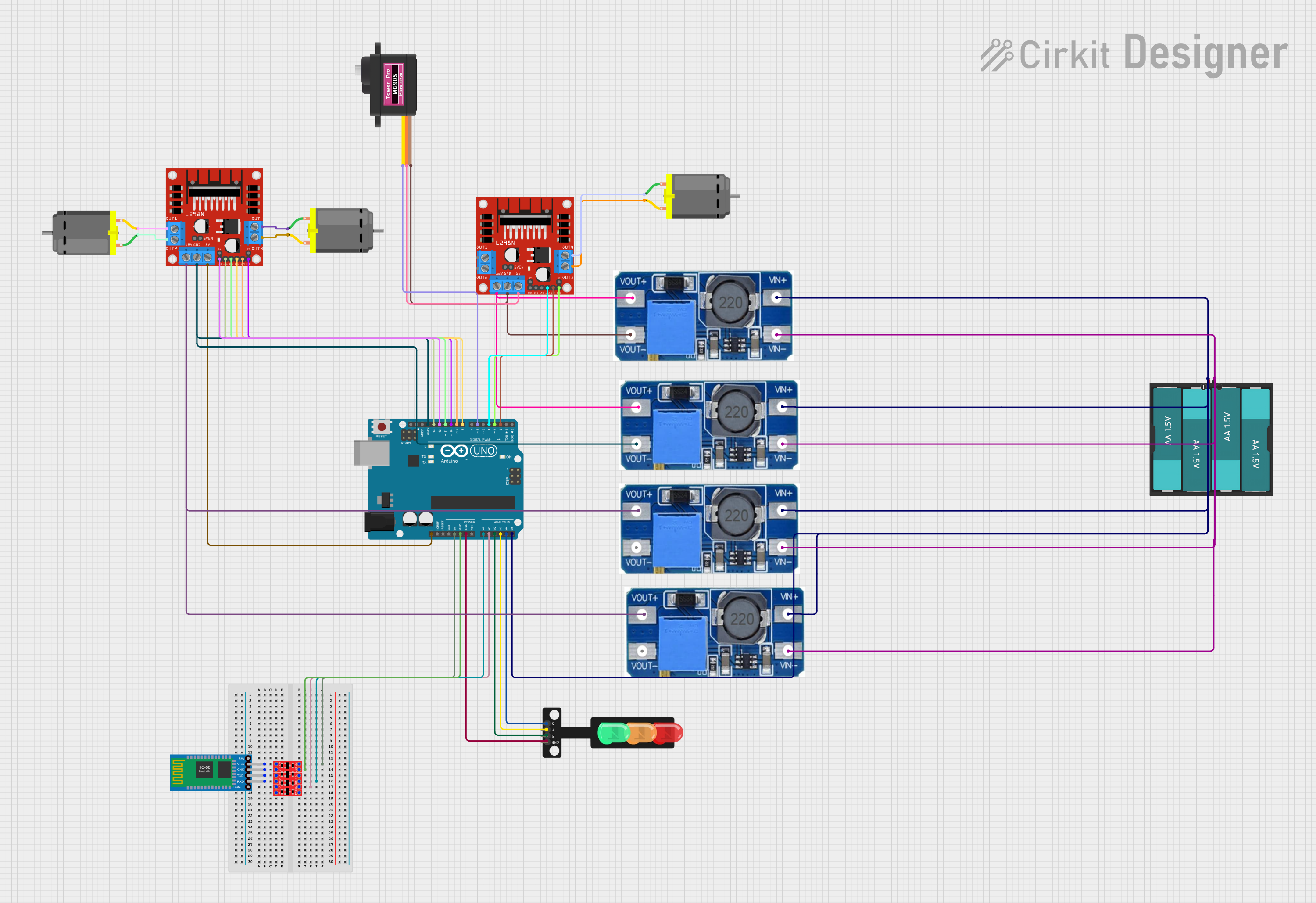
Circuit Documentation
Summary
This circuit is designed to control a set of DC motors and a traffic light using an Arduino UNO microcontroller. The circuit includes motor drivers for controlling the motors, a Bluetooth module for wireless communication, logic level converters for voltage level adjustment, servomotors, and step-up boost power converters for voltage regulation. The Arduino UNO is programmed to interpret Bluetooth commands to drive the motors and control the traffic light, indicating a potential application in robotics or automated systems.
Component List
Arduino UNO
- Microcontroller board based on the ATmega328P
- It has 14 digital input/output pins, 6 analog inputs, a 16 MHz quartz crystal, a USB connection, a power jack, an ICSP header, and a reset button.
DC Motor (x3)
- Electric motor that runs on direct current (DC) electricity.
- Typically used for driving wheels or as actuators in the system.
L298N DC Motor Driver (x2)
- A motor driver module based on the L298N H-bridge.
- It allows for the control of two DC motors simultaneously, enabling forward and reverse directions.
Bluetooth HC-06
- A wireless communication module that allows for serial communication over Bluetooth.
- Used for receiving commands from a Bluetooth-enabled device.
Traffic Light
- A simple module with three LEDs (Red, Yellow, Green) that simulates a traffic light.
- Controlled by the Arduino to demonstrate signal changes.
Step Up Boost Power Converter, Adjustable Voltage Regulator (x4)
- A module that steps up the input voltage to a higher, adjustable output voltage.
- Used to provide the necessary voltage levels to different parts of the circuit.
Bi-Directional Logic Level Converter
- A device that safely steps down 5V signals to 3.3V and steps up 3.3V to 5V at the same time.
- Ensures compatibility between devices operating at different voltage levels.
Servomotor MG90S
- A small and lightweight servo motor capable of precise control.
- Can be used for steering mechanisms or other precision movements.
Battery AAx4 6V
- A battery pack consisting of four AA batteries providing a total of 6V.
- Serves as the power source for the circuit.
Wiring Details
Arduino UNO
5VandGNDare connected to the logic level converter and traffic light.- Analog pins
A0toA4are used for various sensor inputs and control signals. - Digital pins
D2toD13are used to control the motor drivers and servomotor.
DC Motor
- Each motor is connected to a corresponding output on the motor drivers.
L298N DC Motor Driver
IN1,IN2,IN3,IN4,ENA, andENBare connected to the Arduino for motor control.OUT1,OUT2,OUT3, andOUT4are connected to the DC motors.GNDis connected to the Arduino and the step-up boost power converters.12Vinput is connected to the output of the step-up boost power converters.
Bluetooth HC-06
VCCandGNDare connected to the logic level converter for power.TXDandRXDare connected to the logic level converter for communication.
Traffic Light
Red,Yellow, andGreenare connected to the Arduino for control.GNDis connected to the Arduino for a common ground.
Step Up Boost Power Converter, Adjustable Voltage Regulator
VIN+andVIN-are connected to the battery pack for input voltage.VOUT+andVOUT-are connected to the motor drivers and servomotor for output voltage.
Bi-Directional Logic Level Converter
HV1,HV2,HV3,HV4, andGNDare connected to the Arduino.LV1,LV2,LV3,LV4, andGNDare connected to the Bluetooth module.
Servomotor MG90S
SIGis connected to the Arduino for control signals.VCCandGNDare connected to the motor driver for power.
Battery AAx4 6V
VCCis connected to the step-up boost power converters for input voltage.GNDis connected to the Arduino and the step-up boost power converters for a common ground.
Documented Code
#include <SoftwareSerial.h>

// Defining Bluetooth pins (RX, TX)
SoftwareSerial BT(10, 11);

// Defining pins for the motors controlled by the H-bridges
int motorEsquerdaFrente = 3;
int motorEsquerdaTras = 4;
int motorDireitaFrente = 5;
int motorDireitaTras = 6;
int motorFrente = 7; // Pin for the front motor (tool)

void setup() {
  // Setting motor pins as outputs
  pinMode(motorEsquerdaFrente, OUTPUT);
  pinMode(motorEsquerdaTras, OUTPUT);
  pinMode(motorDireitaFrente, OUTPUT);
  pinMode(motorDireitaTras, OUTPUT);
  pinMode(motorFrente, OUTPUT);

  // Starting serial communication with Bluetooth
  BT.begin(9600);
  Serial.begin(9600);  // Communication with the serial monitor (optional)
}

void loop() {
  if (BT.available()) {
    char comando = BT.read();
    Serial.println(comando); // Displays the command on the serial monitor

    // Controls the motors based on the received command
    switch (comando) {
      case 'F': // Forward
        frente();
        break;
      case 'B': // Back
        tras();
        break;
      case 'L': // Left
        esquerda();
        break;
      case 'R': // Right
        direita();
        break;
      case 'S': // Stop
        parar();
        break;
      case 'T': // Activate front motor (tool)
        motorFerramenta(true);
        break;
      case 'X': // Deactivate front motor (tool)
        motorFerramenta(false);
        break;
    }
  }
}

// Functions to control the movement of the cart
void frente() {
  digitalWrite(motorEsquerdaFrente, HIGH);
  digitalWrite(motorEsquerdaTras, LOW);
  digitalWrite(motorDireitaFrente, HIGH);
  digitalWrite(motorDireitaTras, LOW);
}

void tras() {
  digitalWrite(motorEsquerdaFrente, LOW);
  digitalWrite(motorEsquerdaTras, HIGH);
  digitalWrite(motorDireitaFrente, LOW);
  digitalWrite(motorDireitaTras, HIGH);
}

void esquerda() {
  digitalWrite(motorEsquerdaFrente, LOW);
  digitalWrite(motorEsquerdaTras, HIGH);
  digitalWrite(motorDireitaFrente, HIGH);
  digitalWrite(motorDireitaTras, LOW);
}

void direita() {
  digitalWrite(motorEsquerdaFrente, HIGH);
  digitalWrite(motorEsquerdaTras, LOW);
  digitalWrite(motorDireitaFrente, LOW);
  digitalWrite(motorDireitaTras, HIGH);
}

void parar() {
  digitalWrite(motorEsquerdaFrente, LOW);
  digitalWrite(motorEsquerdaTras, LOW);
  digitalWrite(motorDireitaFrente, LOW);
  digitalWrite(motorDireitaTras, LOW);
}

void motorFerramenta(bool ativar) {
  if (ativar) {
    digitalWrite(motorFrente, HIGH);
  } else {
    digitalWrite(motorFrente, LOW);
  }
}
This code is designed to run on an Arduino UNO and controls various motors and a traffic light based on Bluetooth commands. It uses the SoftwareSerial library to create a serial communication channel with the Bluetooth module. The code defines functions for moving forward, backward, left, right, stopping, and controlling an additional front motor (tool). The loop function listens for incoming Bluetooth commands and calls the appropriate movement function.