
Arduino UNO and RFID-RC522 Based Smart Access Control System with Servo and LED Indicators
View and Edit Project In Cirkit Designer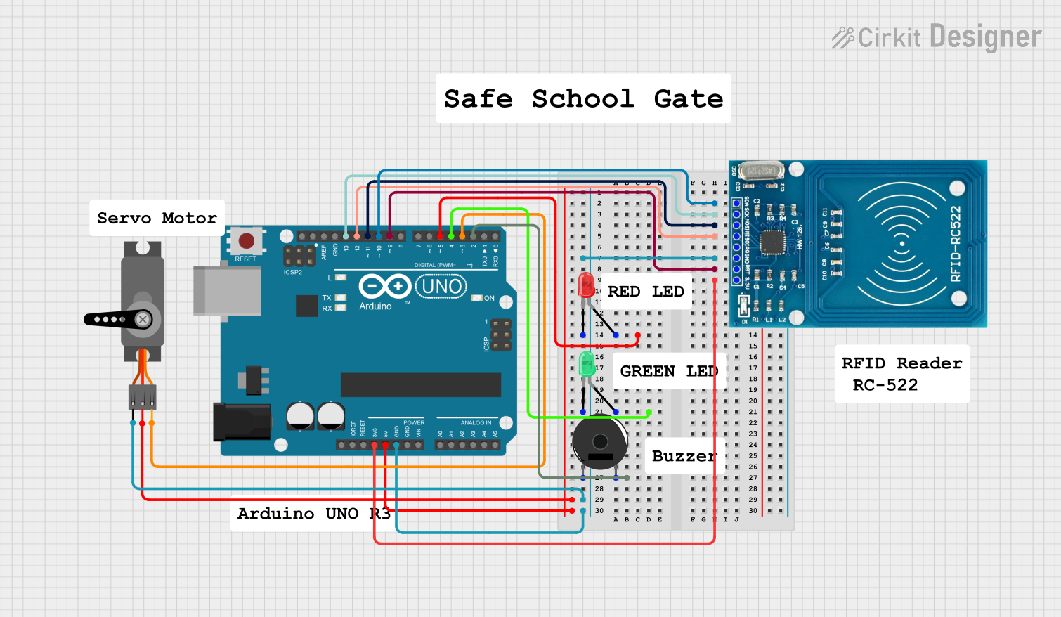
Circuit Documentation
Summary
This document provides a detailed overview of a circuit that integrates an RFID reader, an Arduino UNO, a servo motor, a piezo buzzer, and two LEDs (red and green). The circuit is designed to read RFID tags and perform actions such as moving a servo motor, sounding a buzzer, and lighting up LEDs based on the RFID input.
Component List
RFID-RC522
- Description: RFID reader module
- Pins: VCC (3.3V), RST, GND, IRQ, MISO, MOSI, SCK, SDA
Arduino UNO
- Description: Microcontroller board based on the ATmega328P
- Pins: UNUSED, IOREF, Reset, 3.3V, 5V, GND, Vin, A0, A1, A2, A3, A4, A5, SCL, SDA, AREF, D13, D12, D11, D10, D9, D8, D7, D6, D5, D4, D3, D2, D1, D0
Servo
- Description: Servo motor for precise control of angular position
- Pins: GND, VCC, PWM
Piezo Buzzer
- Description: Sound-producing device
- Pins: pin 1, pin 2
LED: Two Pin (red)
- Description: Red LED for visual indication
- Pins: cathode, anode
LED: Two Pin (green)
- Description: Green LED for visual indication
- Pins: cathode, anode
Wiring Details
RFID-RC522
- SDA connected to Arduino UNO D10
- SCK connected to Arduino UNO D13
- MOSI connected to Arduino UNO D11
- MISO connected to Arduino UNO D12
- GND connected to:
- Piezo Buzzer pin 1
- LED: Two Pin (red) cathode
- LED: Two Pin (green) cathode
- Servo GND
- Arduino UNO GND
- RST connected to Arduino UNO D9
- VCC (3.3V) connected to Arduino UNO 3.3V
Arduino UNO
- D10 connected to RFID-RC522 SDA
- D13 connected to RFID-RC522 SCK
- D11 connected to RFID-RC522 MOSI
- D12 connected to RFID-RC522 MISO
- GND connected to:
- RFID-RC522 GND
- Piezo Buzzer pin 1
- LED: Two Pin (red) cathode
- LED: Two Pin (green) cathode
- Servo GND
- D9 connected to RFID-RC522 RST
- 3.3V connected to RFID-RC522 VCC (3.3V)
- D5 connected to LED: Two Pin (red) anode
- D4 connected to LED: Two Pin (green) anode
- D2 connected to Piezo Buzzer pin 2
- 5V connected to Servo VCC
- D3 connected to Servo PWM
Servo
- GND connected to Arduino UNO GND
- VCC connected to Arduino UNO 5V
- PWM connected to Arduino UNO D3
Piezo Buzzer
- pin 1 connected to RFID-RC522 GND
- pin 2 connected to Arduino UNO D2
LED: Two Pin (red)
- cathode connected to RFID-RC522 GND
- anode connected to Arduino UNO D5
LED: Two Pin (green)
- cathode connected to RFID-RC522 GND
- anode connected to Arduino UNO D4
Documented Code
Arduino UNO Code
void setup() {
  // put your setup code here, to run once:

}

void loop() {
  // put your main code here, to run repeatedly:

}
This code is a basic template for the Arduino UNO. The setup() function is where you initialize your components, and the loop() function is where you place the main logic that runs repeatedly. You can expand this code to include the logic for reading RFID tags, controlling the servo motor, sounding the buzzer, and lighting up the LEDs based on the RFID input.